

Description
- Brand: GE General Electric
- Full Model Number: IS200TBAIH1CCC
- Lifecycle Status: Legacy / installed-base Mark VI component
- Core Function: TBAI Analog Input/Output Terminal Board
- Top 3 Technical Specs: 10 analog inputs; 2 analog outputs; three DC-37 connectors
- System: GE Mark VI Speedtronic Turbine Control
- Board Type: Analog I/O Terminal Board
- Architecture: Simplex or TMR
- Input Options: Current or voltage configurable
- Input Range: 1–20 mA selectable; ±5 VDC / ±10 VDC configurations
- Output Range: 0–20 mA or 0–200 mA
- Transducer Supply: +24 VDC current-limited field power
- Field Termination: Two 24-terminal blocks
- Connectors: JR1, JS1, JT1 DC-37 interfaces
- Associated I/O Processor: GE VAIC / applicable Mark VI analog I/O processor
- Stock & Condition: Exact CCC revision stock confirmation required; New Surplus / Tested Refurbished; Emergency shipping subject to cutoff
GE’s Mark VI/Mark VIe documentation identifies the TBAI family as an analog terminal board supporting 10 analog inputs and 2 analog outputs. The TMR version uses three DC-37 interfaces for redundant I/O-pack or processor connections, while the board’s field inputs can accommodate multiple transmitter wiring arrangements.
Module 3: Obsolescence & Supply Chain Deep Dive
Sourcing a replacement for IS200TBAIH1CCC becomes urgent when a Mark VI analog field interface fails and multiple loops are tied to the same terminal board. The TBAI family provides the field termination point for analog measurements and outputs, supporting 10 AI and 2 AO channels with configurable current/voltage input arrangements. The board also includes noise-suppression circuitry and an identification device that allows the associated controller to verify board type and revision.
From a TCO perspective, replacing the exact terminal board is normally less expensive than migrating the affected analog loops to a new control platform. Existing field wiring, VAIC processor hardware, cabinet layout, and Mark VI application logic can remain intact when the board revision and jumper configuration match. The procurement risk lies in the configuration details: the CCC suffix, simplex/TMR architecture, jumper positions, terminal assignments, and associated processor all need to be checked before release. (Supplier listings for the TBAI family often quote short lead times for available surplus stock, while exact revision availability can vary substantially.)
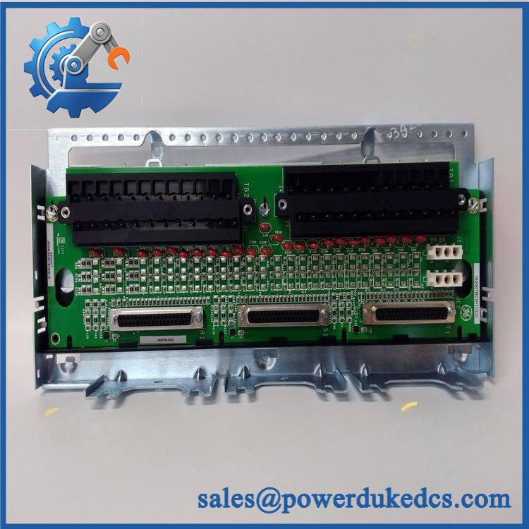
GE IS200TBAIH1CCC
Module 4: Compatibility & Replacement Matrix
| Approval Item | Engineering Assessment |
|---|---|
| Exact Part Replacement | Drop-in Replacement when IS200TBAIH1CCC matches the installed board and architecture |
| Software Compatibility | Configuration-dependent; verify processor assignment, jumper settings, I/O scaling, and field-loop configuration |
| Firmware Flash | Not normally required for the passive terminal board itself |
| Hardware Modification | Normally none for an exact board/configuration match |
| Architecture | Simplex or TMR |
| Analog Inputs | 10 |
| Analog Outputs | 2 |
| Field Terminals | 48 total terminals |
| Processor Connections | JR1 / JS1 / JT1 DC-37 |
| Input Configuration | Current or voltage selectable |
| Output Configuration | 0–20 mA or 0–200 mA |
| Associated Processor | VAIC / applicable Mark VI analog I/O processor |
| Estimated Physical Swap | 1–3 hours |
| Engineering / Commissioning Allowance | 250–1,250 planning range |
| Post-Replacement Testing | Required for every connected analog loop |
Technical references identify the TBAI as a 10-input/2-output analog terminal board. The field interface consists of two 24-terminal blocks, while three DC-37 connectors are used where the architecture requires redundant connections.
⚠️ Field Traps — Watch Out
- Revision and Jumper Mismatch: The board contains configurable jumpers for current/voltage input selection, return/common arrangements, and output-current selection. Photograph every jumper before removal and reproduce the original settings.
- Simplex vs TMR Wiring: In a TMR installation, analog inputs are fanned to the JR1, JS1, and JT1 paths. A board configured for a different architecture cannot be approved solely on physical fit.
Module 5: Quality Assurance & Testing SOP
- OEM anti-counterfeit visual inspection — verify GE markings, complete IS200TBAIH1CCC identification, PCB layout, terminal blocks, connectors, labels, and traceability.
- Revision audit — record the complete CCC suffix and compare it with the installed board.
- Jumper-state documentation — photograph and record all installed jumper positions before energization or reconfiguration.
- Mechanical inspection — inspect both 24-terminal blocks, all three DC-37 connectors, mounting points, PCB edges, and terminal hardware.
- PCB condition inspection — check for corrosion, contamination, overheated components, cracked solder joints, damaged traces, and unauthorized repair.
- Electrical pre-screening — verify continuity, isolation, grounding, and signal-path resistance before applying power.
- Power-on self-test (POST) — install the board with the appropriate Mark VI analog I/O processor and verify normal system initialization.
- Board identification test — confirm the processor correctly recognizes the terminal-board type and revision through the onboard identification device.
- Analog-input simulation — apply calibrated representative current and voltage signals to all required AI channels.
- Channel-scaling verification — test low-, mid-, and high-range points and confirm the expected Mark VI engineering-unit conversion.
- Analog-output testing — command both AO channels and verify the configured 0–20 mA or 0–200 mA output response.
- 24 VDC transmitter-supply test — verify the current-limited field supply on applicable transmitter circuits.
- Terminal continuity testing — verify each active field loop from terminal block through the board interface to the associated processor.
- Noise and stability test — monitor representative loops for drift, intermittent connections, excessive noise, or cross-channel coupling.
- Fault simulation — where supported, simulate open-loop and short-loop conditions and verify expected system diagnostics.
- TMR path verification — for redundant installations, confirm correct fanning and independent signal reception through JR1, JS1, and JT1.
- Configuration-retention test — perform a controlled power cycle and verify board recognition and I/O behavior remain correct.
- Extended energized run — monitor analog stability, terminal temperature, processor diagnostics, and intermittent failures.
- Final QC release — photograph the exact board marking and jumper arrangement, retain channel-by-channel test records, package using ESD protection, and preserve full traceability.
Because the TBAI contains both passive termination hardware and configurable signal-conditioning paths, electrical continuity alone is not enough. The acceptance test should prove board identification, jumper configuration, AI acquisition, AO generation, transmitter power, and processor communication.
Module 6: Procurement & Lifecycle FAQ
Q1. Is GE IS200TBAIH1CCC genuinely in stock, and what is the cutoff for emergency shipping?
Exact availability should be confirmed against IS200TBAIH1CCC, the CCC revision, quantity, condition, and destination before PO release. Current public references show inventory for the broader IS200TBAIH1C family, but exact revision availability varies, so emergency shipment should be based on physical-stock confirmation.
Q2. How do you verify the condition and authenticity of an obsolete ?
Require complete part-number verification, OEM marking inspection, PCB and connector examination, jumper documentation, electrical screening, powered testing with the appropriate analog I/O processor, channel-by-channel AI simulation, AO testing, and terminal continuity checks. The CCC revision should be photographed and retained with the QC record.
Q3. Are there firmware compatibility issues engineers should check before issuing the PO?
The terminal board itself is not the processor, so the primary concern is configuration and processor compatibility rather than a firmware flash on the PCB. Engineers should verify the associated VAIC hardware, simplex/TMR arrangement, jumper positions, field-loop assignments, and Mark VI configuration before commissioning.
Q4. Can another IS200TBAIH1C revision replace ?
Not automatically. The base IS200TBAIH1C designation covers the TBAI function, but the complete suffix defines a specific hardware revision. Match the full board marking, jumper arrangement, field-terminal configuration, processor interface, and installed system architecture before approving a substitute.
Q5. What warranty and return terms should procurement require?
Require a written warranty period, DOA criteria, return-authorization process, serial/part-number traceability, and exclusions for incorrect jumper settings, field wiring errors, electrical overstress, and unauthorized board modification. The quotation should explicitly identify , the verified revision, tested condition, and applicable Mark VI architecture.











 Start Chat


