

Description
- Brand: GE
- Full Model Number: IS200TBCIH1BBC
- Lifecycle Status: Legacy / Obsolete
- Core Function: TBCI Contact Input Terminal Board with Group Isolation
- Top 3 Technical Specs: 24 dry-contact inputs; 125 VDC nominal excitation; Mark VI VME interface with VTCC/VCRC
- Stock & Condition: Physical stock verification required; New Surplus / Tested Refurbished; Emergency dispatch subject to QA release
Module 3: Obsolescence & Supply Chain Deep Dive
A failed GE IS200TBCIH1BBC can remove an entire bank of discrete field inputs from a Mark VI turbine control system. The board belongs to the TBCI Contact Input Terminal Board family and provides 24 dry-contact inputs with group isolation and noise-suppression circuitry. GE documentation identifies the H1 version as the 125 VDC nominal configuration, with an operating excitation range of approximately 100–145 VDC. In Mark VI systems, the board interfaces with the VCCC or VCRC processor hardware through molded cables and supports both Simplex and TMR installations.
For a running Mark VI cabinet, replacing the exact TBCI can be considerably less expensive than converting 24 field contacts to another I/O architecture. Existing field wiring, contact devices, terminal blocks, control logic, and rack hardware can remain in service when the correct TBCI version is restored. That reduces rewiring, engineering labor, commissioning effort, and outage exposure. —The critical procurement point is voltage and platform matching: the H1 configuration is intended for 125 VDC nominal contact excitation, while other TBCI variants use 24 VDC or 48 VDC. The board revision also matters when adapting older Mark VI hardware to related systems.
Module 4: Compatibility & Replacement Matrix
| Replacement Scenario | Classification | Engineering / Procurement Guidance |
|---|---|---|
Exact IS200TBCIH1BBC replacing the same installed board |
Drop-in Replacement | Match full part number, H1 voltage configuration, revision, connectors, and cabinet location |
IS200TBCIH1B with matching H1C/H1B hardware configuration |
Hardware Compatible with Verification | Confirm board revision and Mark VI application |
| 24 VDC or 48 VDC TBCI variant replacing H1 | Hardware Modification | Different contact-excitation range; field-circuit review required |
| Mark VIe C-version TBCI replacing Mark VI B-version hardware | Engineering Review Required | Verify I/O-pack interface and mechanical alignment |
| Different discrete-input terminal board | Hardware Modification | Requires wiring, signal, and configuration review |
GE documentation identifies TBCI versions for 125 VDC, 24 VDC, and 48 VDC contact excitation. It also distinguishes Mark VI and Mark VIe mechanical arrangements.
Estimated switch cost/time: For an exact tested spare already staged on-site, plan approximately 2–4 hours for controlled replacement, 24-channel wiring verification, board recognition, and functional checkout. A newly sourced unit may require 1–5 business days for inspection and expedited transportation. These are planning estimates.
Field Traps — Watch Out
- Excitation voltage mismatch:
IS200TBCIH1BBCbelongs to the 125 VDC nominal TBCI family. A 24 VDC or 48 VDC version may look similar but is not an electrical substitute. - Mark VI vs. Mark VIe: GE documentation states that Mark VI uses TBCI with VTCC/VCRC, while Mark VIe uses TBCI with PDIA I/O packs. The Mark VIe installation also requires the appropriate C-version for mechanical alignment.
- Revision identification: The supplied
BBCsuffix should be retained in the PO and receiving record. Do not approve a genericIS200TBCIH1Bwithout confirming the complete board revision. - 24-channel wiring: Photograph and document every terminal before removal. A single incorrectly landed contact input can create a misleading turbine-control status.
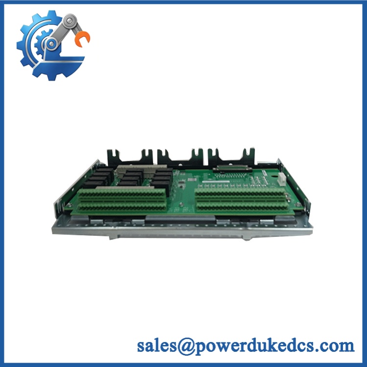
GE IS200TBCIH1BBC
Module 5: Quality Assurance & Testing SOP
The IS200TBCIH1BBC should be qualified as a 24-channel discrete-input interface. A continuity check on the board alone is not sufficient.
- Part-number verification: Confirm
IS200TBCIH1BBC, H1 configuration, revision, serial/traceability information, and GE identification. - OEM anti-counterfeit visual inspection: Inspect GE labels, PCB markings, terminal blocks, connectors, component layout, and evidence of unauthorized rework.
- Physical condition inspection: Check the PCB, terminal blocks, molded cable connectors, mounting hardware, resistors, protection components, and solder joints.
- Terminal inspection: Examine all 24 input terminals for damaged screws, oxidation, contamination, loose hardware, or insulation damage.
- Connector inspection: Check the Mark VI cable interfaces for bent pins, contamination, damaged housings, and retention problems.
- Excitation-path inspection: Verify the board is configured for the correct 125 VDC nominal contact-excitation architecture.
- Continuity testing: Verify applicable input, common, ground, and cable-interface paths before energization.
- Power-on self-test (POST): Install the board in an appropriate Mark VI test assembly and verify expected startup and board recognition.
- Board-ID verification: Confirm the terminal-board identification data is correctly recognized by the associated I/O hardware.
- Input-channel testing: Exercise all 24 contact-input channels independently using controlled dry-contact simulations.
- 125 VDC excitation test: Apply controlled excitation within the approved range and verify correct input-state detection.
- Open/closed-state testing: Test each channel in both open and closed conditions and record the response.
- Noise-suppression verification: Apply representative switching conditions and check for false transitions or unstable input states.
- Debounce/transition testing: Exercise repeated contact transitions and verify stable state recognition.
- Cable-interface test: Verify signal transmission through the associated molded interface cable to the Mark VI processor/I/O hardware.
- Simplex test: Verify correct operation with a single connected processing path where applicable.
- TMR test: Where used in a redundant architecture, verify each associated input path and confirm correct voting behavior at the system level.
- I/O load testing: Exercise multiple contact inputs simultaneously while monitoring supply stability, channel integrity, and board temperature.
- Fault simulation: Introduce controlled open/short input conditions where the approved test procedure permits and verify expected diagnostic behavior.
- Extended observation: Maintain representative input activity to identify intermittent terminals, false transitions, or connector faults.
- Final QC release: Record full part number, revision, excitation voltage, all 24 channel results, board-ID status, photographs, condition grade, test date, and QC authorization.
GE documentation states that TBCI accepts 24 dry contact inputs and includes noise suppression designed to protect against surge and high-frequency noise. The Mark VI H1 configuration is specified for 125 VDC nominal excitation, ranging from 100 to 145 VDC.
Module 6: Procurement & Lifecycle FAQ
Q1. Is the GE genuinely in stock, and what is the cutoff for emergency shipping?
Physical inventory should be verified against the exact marking and revision before the PO is accepted. Emergency dispatch depends on QA completion, warehouse location, carrier pickup, and destination. Same-day shipment should only be confirmed after the actual board has been identified and released.
Q2. How do you guarantee the condition and authenticity of an obsolete ?
Require exact part-number and revision verification, OEM visual inspection, PCB and terminal inspection, controlled excitation testing, all-24-channel input testing, board-ID verification, and documented QC results. Photographs of the actual board and identification markings should remain with the procurement record.
Q3. Can the be used with a 24 VDC contact circuit?
Not as a direct substitution. The H1 TBCI configuration is designed around 125 VDC nominal contact excitation, with a documented range of approximately 100–145 VDC. GE also identifies separate 24 VDC and 48 VDC TBCI versions. Match the installed field-contact voltage before issuing the PO.
Q4. Does the require firmware compatibility checks?
The terminal board itself is not the primary firmware-bearing controller. The important compatibility checks are the Mark VI processor/I/O architecture, board revision, board-ID information, contact-excitation voltage, cable arrangement, and installed configuration. For Mark VIe applications, the appropriate C-version and I/O-pack arrangement must also be confirmed.
Q5. What warranty and return terms should be written into the PO?
Specify warranty duration, DOA coverage, all-24-channel input performance, 125 VDC excitation conformity, terminal and connector condition, board-ID conformity, return authorization, inspection period, and serial-number traceability. For refurbished inventory, require the actual 24-channel functional test record and define whether commissioning-stage failures are covered











 Start Chat


