

Description
- Brand: GE
- Full Model Number: IS200TBCIH2CAA
- Lifecycle Status: Legacy / Obsolescence-risk
- Core Function: Contact Input Terminal Board for GE Mark VI turbine control systems
- Top 3 Technical Specs: 24 dry-contact inputs | 24 VDC nominal excitation | TBCI interface for VCCC/VCRC or PDIA architecture
- Stock & Condition: Physical stock confirmation required | New Surplus / Tested Refurbished by lot | Emergency dispatch subject to inventory and carrier cutoff
Module 3: Obsolescence & Supply Chain Deep Dive
A failed contact-input terminal board can disconnect a large group of field status signals from a turbine controller at once. GE IS200TBCIH2CAA belongs to the TBCI Contact Input Terminal Board family and is associated with the 24 VDC version. GE documentation defines TBCI as a contact-input board accepting 24 dry-contact inputs, with DC power supplied for contact excitation. The inputs include noise-suppression circuitry, while the terminal board provides the field termination interface to the controller architecture. GE documentation also distinguishes the 24 VDC TBCIH2C family from the 125 VDC and 48 VDC versions.
For an installed Mark VI or compatible Mark VIe architecture, replacing the correct TBCI board can avoid rewiring 24 field circuits and changing the broader I/O architecture. The board is a field-interface component rather than the controller processor itself, so restoring the exact hardware can preserve existing terminal assignments, controller configuration, and contact logic. GE specifies the 24 VDC TBCI version for a nominal 24 VDC floating excitation source, with the documented range around 16–32 VDC. (For legacy turbine-control hardware, verified spare inventory can remove a procurement delay when the outage window is fixed.) The TCO case should account for electrician labor, loop checks, field rewiring, control-system verification, and turbine restart testing rather than only the board purchase price.
Module 4: Compatibility & Replacement Matrix
| Purchase Review Item | Engineering Guidance |
|---|---|
| Replacement Classification | Drop-in Replacement — conditional |
| Hardware Modification | None expected for an exact TBCIH2 configuration |
| Primary System | GE Mark VI / compatible Mark VIe control architecture |
| Board Type | TBCI Contact Input Terminal Board |
| Contact Inputs | 24 dry-contact inputs |
| Excitation Voltage | 24 VDC nominal |
| Excitation Range | Approximately 16–32 VDC |
| I/O Architecture | VTCC/VCRC in Mark VI; PDIA-based architecture in Mark VIe |
| Typical Switch Time | ~2–5 labor hours, excluding field loop verification |
| Typical Engineering Cost | Approximately 300–1,200 excluding turbine outage and site travel |
| Recommended Migration Path | Record terminal wiring → verify voltage variant → confirm controller/I/O architecture → replace → verify all 24 inputs → validate control logic |
GE documentation states that TBCI works with VTCC/VCRC in Mark VI and with PDIA I/O packs in Mark VIe, supporting simplex, dual, and TMR configurations. It also identifies TBCIH2C as the 24 VDC version.
Field Traps — Watch Out
- Voltage-variant mismatch: Do not substitute a TBCIH1C or TBCIH3C version for this 24 VDC configuration. GE identifies TBCIH1C as 125 VDC nominal, TBCIH2C as 24 VDC nominal, and TBCIH3C as 48 VDC nominal.
- Mark VI versus Mark VIe interface: The same TBCI family serves different controller architectures. Mark VI uses connections to VCCC/VCRC through the VME rack, while Mark VIe uses PDIA I/O packs mounted directly to the terminal board. Verify the complete installed architecture before approving the replacement.
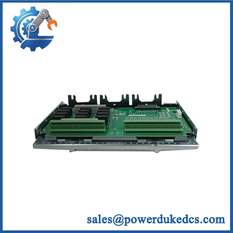
GE IS200TBCIH2CAA
Module 5: Quality Assurance & Testing SOP
A strict pre-shipment inspection for GE IS200TBCIH2CAA should include:
- Identity verification: Confirm the complete IS200TBCIH2CAA marking, TBCI designation, revision suffix, serial information, terminal arrangement, and PCB identifiers.
- OEM anti-counterfeit visual inspection: Examine GE labels, PCB artwork, terminal blocks, connectors, component placement, solder quality, and evidence of unauthorized repair.
- Mechanical inspection: Check both terminal blocks, connectors, mounting hardware, PCB surfaces, fasteners, and shield/grounding provisions for damage or contamination.
- Terminal integrity test: Inspect all field terminals for secure clamping, damaged threads, loose hardware, corrosion, or bent contacts.
- Excitation-power verification: Apply a controlled 24 VDC source within the documented operating range and verify correct board behavior.
- Power-on self-test (POST): Install the board in an approved Mark VI/Mark VIe test arrangement and verify normal initialization and diagnostic status.
- Contact Input 1–24 Testing: Exercise all 24 dry-contact channels independently and verify correct state detection.
- Input-current verification: Check representative input circuits against the documented loading behavior. GE documentation gives approximately 2.5 mA loading for the first 21 circuits on the 24 VDC version, with higher loading on the final three circuits.
- Open-circuit simulation: Simulate an open field contact and verify the expected input-state transition.
- Closed-contact simulation: Apply controlled contact closure and verify reliable state detection.
- Noise-suppression test: Apply representative switching transients within approved limits and confirm stable contact-state detection.
- Controller-interface test: Verify correct communication between the TBCI and the associated VCCC/VCRC or PDIA architecture.
- Redundancy test: Where applicable, verify operation in the installed simplex, dual, or TMR arrangement.
- I/O load testing: Exercise representative contact circuits under controlled conditions while monitoring voltage, current, and terminal temperature.
- Diagnostic test: Verify detection of loss of contact-input excitation and other applicable diagnostics supported by the installed architecture. GE documentation identifies loss of contact-input voltage and non-responding input detection among TBCI diagnostic functions.
- Extended run test: Maintain representative contact states across all channels and monitor for intermittent input changes, noise-related faults, or loss of excitation.
- Final QC: Record serial number, board revision, excitation voltage, all 24 channel results, controller-interface results, diagnostic results, condition grade, photographs, and packaging approval.
This is a field termination board, so the most meaningful QA evidence is channel-by-channel contact-input testing and terminal integrity, not simply a powered-board inspection.
Module 6: Procurement & Lifecycle FAQ
Is GE IS200TBCIH2CAA genuinely in stock, and what is the cutoff for emergency shipping?
Physical inventory should be confirmed against the exact IS200TBCIH2CAA marking before PO release. Emergency dispatch depends on verified stock, payment clearance, export documentation, and the carrier’s daily pickup cutoff.
How do you verify the condition and authenticity of this legacy TBCI board?
Require complete catalog-number and serial verification, OEM visual inspection, terminal-block examination, 24 VDC excitation testing, all-24-channel contact simulation, controller-interface verification, diagnostic testing, and documented final QC.
Can I replace with another TBCI variant?
Not automatically. The TBCI family has distinct voltage versions. GE specifies TBCIH2C for 24 VDC nominal excitation, while TBCIH1C is 125 VDC and TBCIH3C is 48 VDC. The field excitation source must match the replacement board.
Are there firmware compatibility issues I should warn my engineers about before issuing the PO?
Firmware is not normally the primary concern for the terminal board itself. The critical checks are the 24 VDC excitation level, 24 channel assignments, terminal wiring, controller architecture, and associated VCCC/VCRC or PDIA interface. Mark VIe installations also require the correct TBCI mechanical/interface version for the I/O pack arrangement.
What warranty and return terms should procurement require?
The quotation should specify the exact part number, revision, condition grade, serial traceability, 24-channel test scope, warranty period, DOA coverage, and return authorization procedure. For a turbine-control contact board, acceptance should be tied to documented input-channel testing and the exact installed voltage configuration.











 Start Chat


