

Description
- Brand: GE
- Full Model Number: IS200TBCIH2CCD
- Base Assembly: IS200TBCIH2C
- Lifecycle Status: Legacy Mark VI platform; current OEM production status requires verification
- Core Function: Contact Input Group Isolation terminal board
- System: GE Mark VI Speedtronic turbine control
- Input Channels: 24 dry contact inputs
- Nominal Input Supply: 24 VDC for the H2 configuration
- Input Filtering: Approximately 4 ms hardware filter
- Input Loading: 2.5 mA per point for inputs 1–21; 10 mA for inputs 22–24
- Terminal Blocks: TB1 and TB2
- I/O Connections: JR1, JS1 and JT1 for controller/I/O processor connections
- Power Connections: JE1 and JE2
- Hardware Settings: No jumpers or adjustable hardware settings
- Stock & Condition: Verify New Original / New Surplus / Tested Refurbished condition before quotation
Obsolescence & Supply Chain Deep Dive
The GE IS200TBCIH2CCD is a Mark VI Contact Input Group Isolation (TBCI) terminal board used to terminate and condition discrete contact signals in GE Speedtronic turbine-control systems. Public technical documentation for the underlying IS200TBCIH2C identifies 24 contact-input channels, two barrier-type terminal blocks, three DC-37 cable connections, two power-input connectors, input filtering and surge/noise suppression. The H2 configuration uses the lower-voltage contact-excitation architecture associated with the 24 VDC class of TBCI boards.
The lifecycle risk is primarily associated with maintaining an installed Mark VI control cabinet rather than finding a generic 24-point digital-input replacement. The TBCI board is part of the field-wiring and I/O architecture, and the exact suffix matters. A replacement with the wrong voltage configuration or connector arrangement can create commissioning work even when the board appears physically similar. For a turbine shutdown spare, retaining the complete IS200TBCIH2CCD identification and verifying the installed board before procurement can avoid unnecessary wiring changes and control-system validation. (For critical contact inputs, serial-specific inspection and functional testing should be requested before dispatch.)
Compatibility & Replacement Matrix
| Replacement Scenario | Classification | Engineering Assessment | Typical Labor / Downtime Planning |
|---|---|---|---|
| Exact IS200TBCIH2CCD replacement | Drop-in Replacement | Preferred option when the complete board identification, revision and Mark VI application match the installed unit | Approximately 1–3 hours for replacement and input verification |
| IS200TBCIH2C with matching H2 configuration and compatible revision | Drop-in Replacement — Verify Revision | The base IS200TBCIH2C designation corresponds to the same TBCI board family. Confirm the complete suffix and physical labeling before installation | Approximately 1–4 hours |
| Different TBCI H2 revision | Software Compatible / Hardware Verification Required | Verify connector arrangement, excitation voltage, I/O processor compatibility and application configuration. Do not assume all H2 revisions are interchangeable solely from the family name | Approximately 2–6 hours |
| TBCI board with different voltage/configuration suffix | Hardware Modification | Field excitation and input characteristics may differ. Engineering review and loop-by-loop verification are required | Approximately 4–12+ hours |
| Generic 24-channel digital-input module | Hardware Modification | Not a direct substitute because the existing Mark VI wiring, cable interface, diagnostics and I/O architecture must be preserved or redesigned | Approximately 8–24+ hours |
Field Traps — Watch Out
Verify the H2 voltage configuration.
The TBCI family contains different hardware variants. Public documentation for the IS200TBCIH2C identifies the H2 configuration with lower-voltage excitation, while the H1 configuration uses a substantially higher DC input architecture. Do not substitute between H1 and H2 variants based only on the number of inputs.
The full suffix is part of the procurement specification.
The requested IS200TBCIH2CCD is also commonly cataloged around the base IS200TBCIH2C designation. Some supplier databases omit the final revision/variant characters. Procurement and incoming inspection should use the complete marking from the installed board rather than shortening the PO description.
Do not confuse terminal capacity with input count.
The two terminal blocks are described as having 24 screw connections each, while the board provides 24 contact-input channels. The terminal arrangement should be checked against the cabinet wiring diagram before removal.
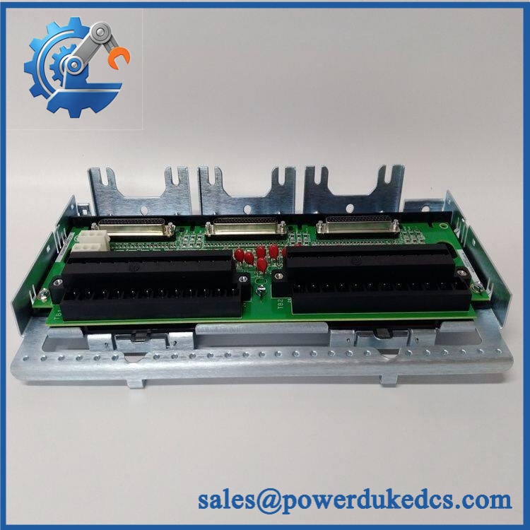
GE IS200TBCIH2CCD
Quality Assurance & Testing SOP
The IS200TBCIH2CCD should be evaluated as a complete Mark VI termination assembly. A visual check alone is not sufficient for a shutdown-critical spare.
Identity and physical inspection
- Verify the complete marking
- Record serial number and board revision where available
- Compare the board with the requested family
- Inspect TB1 and TB2 terminal blocks
- Check all screw terminals for mechanical damage
- Inspect JR1, JS1 and JT1 connectors
- Inspect JE1 and JE2 power connectors
- Check the metal frame and shield terminal strip
- Inspect PCB components for corrosion, contamination or physical damage
- Photograph identification labels before shipment
Electrical inspection
- Verify expected H2 excitation-voltage architecture
- Check for abnormal resistance or short conditions
- Inspect input protection components
- Check terminal-to-ground conditions
- Verify power connector integrity
- Confirm there are no unauthorized jumpers or hardware modifications
The documented architecture has no hardware jumpers or adjustable settings. Each contact input has filtering intended to reduce high-frequency noise and suppress transient disturbances.
Functional input testing
- Install the board in a suitable Mark VI test configuration
- Apply the correct contact-excitation supply
- Test all 24 input channels individually
- Simulate open and closed contact states
- Verify input-state detection
- Check inputs 1–21 at the specified lower current loading
- Check inputs 22–24 at their specified higher current loading
- Confirm expected hardware filtering behavior
- Verify I/O processor communication
- Test JR1 in a simplex configuration where applicable
- Test JR1/JS1/JT1 connections in a TMR configuration where applicable
The documented TBCI architecture supports simplex and TMR applications, with the board connected to Mark VI I/O processors through the applicable cable connections.
Diagnostic verification
- Verify excitation-voltage monitoring
- Check contact-input fault detection
- Confirm expected failsafe behavior
- Verify board identification through the connected I/O system
- Check TMR input comparison where applicable
- Record any diagnostic alarms during testing
Final release inspection
- Record serial number and revision
- Attach the functional test record
- Photograph terminal and connector condition
- Apply ESD protection
- Protect terminal blocks against impact during transport
- Use shock-resistant export packaging
Procurement & Lifecycle FAQ
What is the GE ?
The is a GE Mark VI Contact Input Group Isolation terminal board, associated with the TBCI family. It provides termination and conditioning for discrete contact inputs used by the Mark VI turbine-control system.
How many inputs does the support?
The underlying TBCI design provides 24 contact-input channels. The inputs are connected through two barrier-type terminal blocks, with the exact field wiring determined by the installed Mark VI configuration.
What voltage does the H2 version use?
The H2 configuration belongs to the lower-voltage TBCI architecture and is documented around a 24 VDC nominal supply. The exact excitation arrangement should be verified against the installed cabinet drawings before energizing a replacement.
Is the same as ?
The complete identification should be retained for procurement. Public listings commonly shorten the product to , but the additional characters can identify a particular revision or configuration. The physical label and installed documentation should control the replacement decision.
What should be confirmed before purchasing a replacement?
Provide the complete board number, hardware revision, serial number if available, cabinet/application information, input voltage, simplex or TMR architecture, connector configuration and required condition. For a critical turbine-control spare, request serial-specific photographs plus documented testing of all 24 contact inputs before shipment.











 Start Chat


