

Description
- Model & Brand: IS200TDBTH6ACD / GE
- Series: Mark VIe Speedtronic
- Part Type: TDBT Discrete Input/Output Terminal Board
- Functional Role: Contact-input acquisition and relay-output termination
- Input Capacity: 24 group-isolated contact inputs
- Relay Outputs: 12 Form-C relay outputs
- Input Wetting Voltage: 24, 48, or 125 VDC, configuration dependent
- Approx. Physical Dimensions: Approx. 260 × 125 × 53 mm (D × H × W) according to current supplier data
- Estimated Shipping Weight: Approx. 0.8–1.2 kg packed; verify actual packaged weight before freight booking
- Terminal Arrangement: Two barrier-style terminal blocks
- I/O Pack Interface: Three PDIO connections for Simplex, Dual, or TMR architectures
- What’s in the Box: TDBT terminal board; mounting hardware when supplied; ESD protection; documentation only when specifically included
- Mounting: DIN rail or flat-panel mounting
- Storage Priority: ESD protection, dry storage, and preservation of terminal/connector condition
GE’s Mark VIe documentation describes the TDBT as a contact-input/output terminal board supporting Simplex, Dual, or TMR configurations, while current records identify IS200TDBTH6ACD as the TDBT board with 24 contact inputs and 12 Form-C relay outputs.
Product Introduction
The TDBT is where a large number of field contact signals physically enter and leave the Mark VIe control architecture. IS200TDBTH6ACD provides 24 group-isolated contact inputs and 12 Form-C relay outputs, with the board accepting externally supplied wetting power at nominal 24, 48, or 125 VDC. Three PDIO I/O pack interfaces allow the board to participate in Simplex, Dual, or TMR architectures.
For warehouse control, the distinction between this board and the newer IS200TDBTH6A matters. Current supplier records identify the IS200TDBTH6ACD as superseded by IS200TDBTH6A, but a superseding part number should not automatically be treated as a field-equivalent replacement without checking the project drawing and I/O-pack configuration. The ACD revision is therefore the identity that should remain on the asset label (especially when several Mark VIe terminal-board variants are stored together).
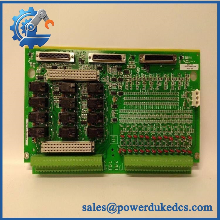
GE IS200TDBTH6ACD
Core Technical Specifications
| Parameter | Value |
|---|---|
| Manufacturer | General Electric |
| Part Number | IS200TDBTH6ACD |
| Series | Mark VIe Speedtronic |
| Functional Acronym | TDBT |
| Board Type | Discrete Input/Output Terminal Board |
| Input Channels | 24 group-isolated contact inputs |
| Relay Outputs | 12 Form-C outputs |
| Wetting Voltage | 24 / 48 / 125 VDC nominal, configuration dependent |
| 24 VDC Input Range | 16–32 VDC |
| 48 VDC Input Range | 32–64 VDC |
| 125 VDC Input Range | 100–145 VDC |
| Input Current | 2.5 mA for channels 1–21; 10 mA for channels 22–24 |
| AC Rejection | 12 V RMS |
| Input Filtering | Hardware filtering and noise suppression |
| Relay Contact Type | Form-C |
| Relay Contact Rating | Up to 5 A at 250 VAC according to supplier records |
| PDIO Connections | 3 |
| Architecture | Simplex, Dual, or TMR |
| Main Supply | +5 VDC through host I/O architecture |
| Mounting | DIN rail or flat panel |
| Reported Dimensions | Approx. 260 × 125 × 53 mm |
| Estimated Net Weight | Approx. 0.5–0.7 kg, supplier dependent |
| Operating Temperature | Verify exact system specification; supplier records report approximately -30 to +65°C |
| Firmware | No standalone firmware package |
| Lifecycle | Legacy / superseded by IS200TDBTH6A in some supplier records |
GE’s official Mark VIe safety documentation confirms the broader TDBT architecture, including 24 inputs, selectable wetting-voltage arrangements, Simplex/Dual/TMR operation, and PDIO I/O packs.
🚨 Global Compliance & Industry Certifications
For IS200TDBTH6ACD, certification claims should be tied to the complete Mark VIe system and exact installation configuration, not inferred from the PCB alone.
- CE Mark: May apply at the complete Mark VIe equipment/system level. Independent board-level CE conformity should not be claimed without GE documentation.
- UL/cUL: Do not claim independent UL/cUL listing for the bare board unless the supplied revision is covered by the applicable GE certification.
- ATEX / IECEx: Mark VIe equipment can have hazardous-location configurations, but no independent ATEX/IECEx approval should be attributed to without revision-specific evidence.
- Class I, Division 2 / Zone 2: Hazardous-location suitability depends on the complete approved Mark VIe architecture, installation method, I/O pack, enclosure, and wiring arrangement.
- Marine Approvals: No independent DNV, ABS, or Lloyd’s Register approval was established for this exact board from the reviewed records.
- EMC: TDBT includes input filtering and surge/noise suppression, but EMC compliance should be evaluated for the complete Mark VIe cabinet.
Why this matters: Contact inputs may connect to field switches, permissives, interlocks, and protection circuits, while relay outputs may operate external control functions. Incorrect voltage selection or an uncertified hardware substitution can therefore create both functional and compliance exposure.
Verify specific lot certifications with OEM.
🚨 Long-Term Storage & Asset Preservation Guide
Keep the TDBTH6ACD in an ESD shielding bag. The terminal board has exposed connectors, terminal interfaces, and electronic components. Store it in rigid packaging so the terminal blocks and I/O-pack connectors cannot be struck during warehouse movement.
Keep the board dry and avoid condensation. A practical long-term warehouse target below 60% RH is preferable, even where the broader equipment specification permits higher non-condensing humidity. Contact oxidation is a particular concern because an intermittent terminal connection can look like a field-switch failure after installation.
Preserve the wetting-voltage configuration with the board. The TDBT architecture supports 24, 48, and 125 VDC contact excitation arrangements. Record the installed voltage class and wiring drawing with the asset rather than assuming a replacement board can be connected to any available DC source.
Before energization after multi-year storage, allow the sealed package to stabilize to cabinet temperature. Then inspect the barrier terminals, connectors, relay contacts, PCB surface, mounting hardware, and any areas showing oxidation or contamination.
Physical Installation Prerequisites
- Host System: Install in the approved GE Mark VIe terminal-board architecture.
- I/O Pack: Confirm the compatible PDIO I/O pack and the installed Simplex, Dual, or TMR configuration before installation.
- Mounting: The board can use DIN-rail or flat-panel mounting, depending on the carrier arrangement. Verify the actual cabinet assembly before removing the existing unit.
- Wetting Voltage: Confirm whether the field circuits use 24, 48, or 125 VDC. Never energize a contact-input terminal with an assumed voltage.
- Terminal Blocks: Label every field wire before removal and compare the wiring against the approved cabinet drawing.
- Relay Outputs: Verify every Form-C contact designation and external voltage before energizing the relay circuits.
- PDIO Links: Inspect all three I/O-pack connectors for bent pins, contamination, or incomplete seating.
- Grounding: Preserve the Mark VIe cabinet grounding and shield arrangement.
- Clearance: Maintain front access for terminal wiring and sufficient rear/side space for connector engagement; follow the actual cabinet drawing rather than applying an arbitrary clearance dimension.
- Cooling: Preserve the designed cabinet airflow. Do not bundle field wiring tightly across electronic surfaces.
- ESD: Use a grounded wrist strap and ESD-safe work surface.
- Power Isolation: Use the approved GE maintenance and lockout procedure before disturbing field wiring or the terminal board.
Buyer’s FAQ
Q1. What HS Tariff Code should be used for ?
Do not assign a final HS code from “terminal board” alone. This is a dedicated industrial control-system assembly, and classification can vary by destination country and by whether customs treats the item as a part of electrical control equipment. Have the broker review the technical function, invoice description, and local tariff schedule before export.
Q2. What should the Country of Origin file contain?
Use the actual manufacturing origin supported by supplier or manufacturer records. The country from which the spare is shipped is not automatically its COO. Retain the commercial invoice, packing list, COO statement or certificate where applicable, physical nameplate photograph, and revision/serial information for the compliance file.
Do not assume it can. The board is connected to field contact circuits and relay outputs carrying externally supplied voltages. Use the approved Mark VIe maintenance procedure and isolate the relevant field circuits before removal unless the exact installation procedure specifically authorizes live intervention.
Q4. Does a New Original include the latest firmware?
No standalone firmware should be expected for the terminal board itself. The programmable element is the associated PDIO I/O pack, while TDBT provides field termination and signal-interface functions. The board’s critical identity is its exact revision and its compatibility with the selected I/O pack.
Q5. Is still the preferred procurement number?
Treat it as a legacy/superseded asset requiring revision control. Current supplier records identify IS200TDBTH6A as a successor to , but the newer number should be approved only after GE documentation confirms the electrical, mechanical, I/O-pack, and project-configuration compatibility.











 Start Chat


