

Description
- Model: IS200VRTDH1D
- Brand: GE General Electric
- Series: Mark VI Speedtronic
- Board Type: VRTD VME RTD Input Board
- Functional Acronym: VRTD
- Functional Revision: D
- PCB Construction: Conformal-coated multilayer PCB
- Input Capacity: 16 RTD channels per VRTD board
- Sensor Connection: Three-wire RTD architecture through TRTD or DRTD terminal board
- Supported RTD Types: 10 Ω, 100 Ω, and 200 Ω platinum; 10 Ω copper; 120 Ω nickel
- A/D Resolution: 14-bit
- Normal Scan Time: 250 ms / 4 Hz
- Fast Scan Time: 40 ms / 25 Hz
- Multiplexed Excitation: 10 mA DC excitation per RTD
- Approx. Board Dimensions: Secondary records vary; verify the actual PCB before freight booking
- Estimated Shipping Weight: Secondary inventory records vary substantially; use the actual packed unit for freight calculation
- Mounting: Mark VI VME rack
- What’s in the Box: IS200VRTDH1D board only unless the PO explicitly includes TRTD/DRTD terminal hardware, cables, or mounting accessories
- Packaging: ESD shielding bag, card-edge protection, rigid support, moisture-controlled outer carton
The IS200VRTDH1D is documented as a VME Resistance Temperature Device input board that accepts sixteen three-wire RTD inputs through a separate terminal-board architecture.
Product Introduction
Structure A — Environmental Hook
Temperature-input hardware in turbine cabinets operates amid vibration, electrical noise, temperature cycling, and long cable runs from field sensors. The GE IS200VRTDH1D converts RTD signals into digital temperature values for the Mark VI control system, supporting 16 three-wire RTD channels with a 14-bit A/D converter. The RTDs are wired to a separate TRTD or DRTD terminal board, then connected to the VRTD board through dedicated cables.
For asset management, the terminal board and VME card should be tracked as a matched signal chain. GE documentation specifies a 10 mA multiplexed excitation current to each RTD and permits cable runs up to 300 m / 984 ft, with a maximum two-way cable resistance of 15 Ω. Those values matter during troubleshooting because a field-cable problem can look like a failed VRTD board (particularly after years of plant operation).
| Parameter | Value |
|---|---|
| Manufacturer | GE General Electric |
| Part Number | IS200VRTDH1D |
| Series | Mark VI Speedtronic |
| Functional Acronym | VRTD |
| Product Type | VME RTD Input Board |
| Functional Revision | D |
| Input Channels | 16 RTD channels |
| RTD Wiring | Three-wire |
| RTD Types | 10/100/200 Ω platinum, 10 Ω copper, 120 Ω nickel |
| Analog Span | 0.3532–4.054 V |
| A/D Resolution | 14-bit |
| Normal Scan | 250 ms / 4 Hz |
| Fast Scan | 40 ms / 25 Hz |
| RTD Excitation | 10 mA DC multiplexed excitation |
| Input Terminal Board | TRTD or DRTD |
| Data Transfer | VME backplane to VCMI and controller |
| Cable Distance | Up to 300 m / 984 ft |
| Maximum Two-Way Cable Resistance | 15 Ω |
| Power Consumption | Less than 12 W |
| Processor Function | VRTD temperature acquisition and digital conversion |
| Memory | No standalone user-memory specification published |
| Firmware | System/application dependent |
| PCB Coating | Conformal coating |
| Mounting | VME card |
| Power Draw | <12 W published for the board |
| Heat Dissipation | Up to approximately 12 W at the stated maximum board consumption |
| Dimensions | Verify actual board; secondary sources conflict |
| Weight | Verify actual unit; secondary records conflict |
| Lifecycle Profile | Legacy Mark VI hardware |
GE’s Mark VI documentation specifies the 14-bit conversion, 250 ms normal scan, 40 ms fast scan, RTD types, and <12 W power consumption.
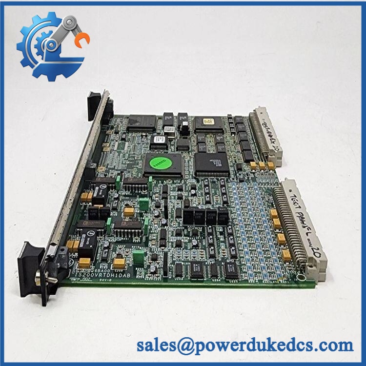
GE IS200VRTDH1D
🚨 Global Compliance & Industry Certifications
- CE Mark: Do not make a standalone CE claim for the PCB unless the applicable GE declaration covers the exact equipment configuration.
- UL/cUL: Verify the Mark VI cabinet certification and applicable board revision before making a UL/cUL claim.
- ATEX / IECEx: Do not assume hazardous-area certification. The VRTD card is installed inside a Mark VI control architecture; field-area certification depends on the complete installation.
- Marine Approvals: No revision-specific marine certification was established for the exact IS200VRTDH1D.
- Functional Safety: Do not assign a standalone SIL rating to the VRTD board. Any safety claim belongs to the complete turbine-control/protection architecture.
- Electrical Safety: VRTD field circuits use RTD excitation and long field wiring; cabinet isolation remains mandatory before servicing.
- Environmental Construction: The conformal-coated PCB provides additional protection against contamination, but it does not eliminate ESD or moisture-control requirements.
- Audit Documentation: Retain the exact part number, revision, terminal-board type, serial/date code, supplier COO, inspection record, and applicable certification documents.
Verify specific lot certifications with OEM.
🚨 Long-Term Storage & Asset Preservation Guide
Keep the VRTD card inside an ESD shielding bag. The VME card edge and analog measurement circuitry are sensitive to static discharge and connector contamination.
Protect the card edge and terminal interfaces. Keep the mating contacts capped where possible. Never place the board directly on conductive shelving or allow packing material to contact exposed contacts.
Control humidity and condensation. A clean, dry warehouse below approximately 60% RH is a practical preservation target when the exact OEM storage specification is unavailable. Use sealed packaging and suitable desiccant while avoiding direct sunlight and rapid temperature cycling.
Preserve the associated TRTD/DRTD relationship. Record which terminal-board architecture the spare is intended to support. GE documentation distinguishes the VRTD processor board from the TRTD termination board, so a warehouse label reading only “RTD board” is insufficient.
Do not repeatedly energize stored boards merely for inventory checks. Record the last validated test date instead.
Physical Installation Prerequisites
- VME Rack: Install the VRTD in the designated Mark VI VME rack position.
- Terminal Board: Confirm the associated TRTD or DRTD board before installation.
- Cable Interface: Verify the molded cable connections between the terminal board and VME rack.
- RTD Wiring: Confirm three-wire RTD connections, excitation, signal, and return conductors.
- Cable Length: Where long field runs are used, verify the documented maximum 300 m / 984 ft distance and 15 Ω maximum two-way resistance.
- Sensor Type: Confirm the installed RTD material and resistance range before commissioning.
- Shielding: Maintain the approved RTD cable shielding and cabinet termination arrangement.
- VME Connector: Inspect card-edge contacts for oxidation, contamination, or mechanical damage.
- Grounding: Follow the Mark VI cabinet grounding scheme.
- Cooling: Keep VME rack airflow unobstructed; do not compress wiring against the card.
- ESD: Use grounded ESD controls whenever handling the PCB.
- Service Clearance: Leave sufficient access for card removal and inspection of the terminal-board connectors.
- Commissioning: Validate representative temperature channels against calibrated resistance sources before returning the turbine system to service.
GE documentation states that the VRTD receives signals from the RTD termination board, converts them into digital temperature values, and transfers those values through the VME backplane to the VCMI and controller.
Buyer’s FAQ
Q1. What HS tariff code should be used for GE ?
Do not classify it simply as a generic PCB. The is a dedicated RTD temperature-input board for GE Mark VI turbine control, so the final tariff classification should reflect its specialized electrical-control function.
For the commercial invoice, use a precise description such as “GE Mark VI VME RTD Input Board, 16-channel temperature acquisition card” and have the importer or customs broker confirm the final national HS code.
Q2. What Country of Origin should appear on the COO?
Use the actual manufacturing origin of the physical board, supported by its nameplate and supplier traceability. Current secondary inventory records commonly report USA, but the actual unit should control the COO statement.
Retain the actual-unit photograph, serial/date-code information, supplier COO, and commercial invoice together.
Q3. Should I insure shipment of ?
Yes, when the VRTD is a critical turbine spare. Protect the VME card edge, PCB corners, connectors, and mounting hardware against shock and compression.
Photograph the complete board, revision marking, serial information, card edge, and packaging before dispatch.
Q4. Does include the latest firmware pre-loaded?
Do not assume it does. The VRTD performs temperature acquisition within the Mark VI architecture, and the installed system software/configuration determines how the board is integrated. Before commissioning, verify the board revision and system software baseline.
Q5. Can be replaced by a TRTD board?
No. They perform different functions. The VRTD is the VME processor/input board, while the TRTD/DRTD is the field termination board to which the RTDs are wired. GE’s architecture requires the appropriate terminal-board-to-VME connection for the RTD installation.











 Start Chat


