

Description
- Model: IS200VTURH1B
- Brand: GE
- Series: Mark VI IS200
- Part Type: VME Turbine Protection Board
- Functional Designation: VTUR
- Core Function: Processes turbine speed and protection signals and participates in the primary overspeed trip system.
- Architecture: Mark VI VME
- Board Format: VME
- Primary Application: Gas turbine speed monitoring and turbine protection
- Associated Terminal Boards: TTUR and TRPG families
- Primary Protection Function: Overspeed detection and primary trip relay control
- Additional Functions: Shaft-current/shaft-voltage monitoring and applicable flame-detection interfaces
- Relays: K25 and K25P identified in published hardware descriptions
- PCB Coating: Conformal coated
- Hardware Revision: B
- Functional Revision: A
- Artwork Revision: C
- Reference Manual: GEH-6721L is identified by secondary technical documentation.
Product Introduction
A turbine protection failure is fundamentally different from a routine monitoring-point failure because the affected hardware participates in detection of abnormal speed and protective trip conditions. The GE IS200VTURH1B is a Mark VI VTUR VME turbine protection board used for turbine speed measurement and the primary overspeed protection function. Technical references identify it as a Mark VI, rather than Mark VIe, component.
The VTUR board works with the associated terminal-board architecture rather than operating as a generic standalone I/O card. Documented functions include processing turbine-speed signals, generating the primary overspeed-trip command path, monitoring induced shaft current and voltage, and supporting applicable turbine flame-detection functions. In gas-turbine systems, the board interfaces with the TRPG/TTUR architecture and related trip hardware.
Core Technical Specifications
| Parameter | Specification |
|---|---|
| Manufacturer | GE |
| Part Number | IS200VTURH1B |
| Product Family | Mark VI IS200 |
| Functional Acronym | VTUR |
| Product Type | VME Turbine Protection Board |
| Primary Function | Turbine speed monitoring and primary overspeed protection |
| System Architecture | Mark VI |
| Board Interface | VME |
| Hardware Form Revision | B |
| Functional Revision | A |
| Artwork Revision | C |
| PCB Construction | Conformal coated |
| Associated Terminal Boards | TTUR, TRPG |
| Gas Turbine Trip Interface | TRPG / related emergency-trip architecture |
| Primary Overspeed Trip | Supported |
| Shaft Current Monitoring | Supported |
| Shaft Voltage Monitoring | Supported |
| Flame Detection Interface | Supported in applicable configurations |
| Front-Panel Diagnostics | Status LEDs |
| Identified Relays | K25, K25P |
| Firmware | Board-level embedded protection/processing; no user application firmware comparable to a Mark VI controller |
| Installation | VME rack |
| Mark VIe Direct Replacement | No — not a direct Mark VIe substitute |
| Reference Documentation | GEH-6721L cited by technical references |
Public technical sources consistently identify IS200VTURH1B as a Mark VI VTUR VME turbine protection board and associate it with TTUR/TRPG terminal-board families. The published hardware revision information is B/A/C for hardware, functional, and artwork revisions respectively.
Exact channel counts, voltage levels, dimensions, and board-level electrical thresholds should be taken from the applicable GE Mark VI documentation for the installed VTUR configuration rather than inferred from the part number.
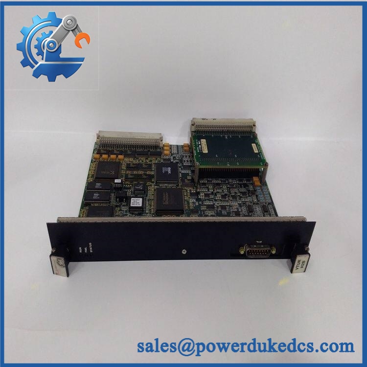
GE IS200VTURH1B
Application Scenarios & Pain Points
Gas Turbine Speed Protection
The VTUR’s principal role is turbine-speed processing and the generation of the primary overspeed trip. World of Controls specifically describes the board as measuring turbine speed and controlling the primary overspeed trip relays associated with the trip terminal-board architecture.
Primary Turbine Trip Systems
The VTUR is part of the interface between the Mark VI controller’s calculated overspeed-trip logic and the physical trip-solenoid circuitry. In applicable configurations, the VTUR passes the trip command toward the appropriate TRPx/TRPG architecture, which then interfaces with the emergency-trip devices.
Shaft Current and Voltage Monitoring
Published technical descriptions also identify monitoring of induced shaft current and shaft voltage, including alarm functions for excessive values. This makes VTUR relevant to both protective logic and turbine-condition monitoring.
Flame Detection on Applicable Gas Turbines
Certain gas-turbine configurations use VTUR-related circuitry for flame-detection interfaces. This is configuration-dependent and should be verified against the plant’s Mark VI hardware documentation before assuming a particular flame-detector interface is populated.
Legacy Mark VI Maintenance
The IS200VTURH1B belongs to the legacy Mark VI IS200 VME platform. That distinction is important during procurement because later Mark VIe systems use a different I/O and controller architecture. A visually similar modern turbine I/O module is not automatically compatible with an IS200 VTUR installation.
Common Error Codes & Diagnostic Symptoms
Symptom: Turbine speed signal is missing or implausible
→ Diagnosis: Check the speed sensors, field wiring, TTUR terminal board, VTUR connectors, and VME rack power before condemning the VTUR board. Multiple sensor-related problems should not be assumed to originate inside the processor card.
→ Action: Replace module after the field and terminal interfaces have been verified.
Symptom: Primary overspeed trip path reports an abnormal condition
→ Diagnosis: Inspect the VTUR status indications, associated trip terminal board, relay interface, and controller-side trip command. The VTUR participates in the primary overspeed protection path, so a trip-interface failure requires system-level isolation.
→ Action: Replace module after confirming the external trip circuitry.
Symptom: Shaft-current or shaft-voltage monitoring becomes unavailable
→ Diagnosis: Verify the associated sensor/measurement wiring and terminal-board connections before replacing the VTUR. Published descriptions identify these monitoring functions as part of the VTUR role.
→ Action: Replace module after isolating the fault to the board.
No specific numerical GE fault code is assigned here because a sufficiently authoritative code table for the IS200VTURH1B itself was not verified.
Cross-Reference & Lifecycle Migration
The most important compatibility reference is the TTUR/TRPG terminal-board family. Technical documentation identifies as being used with specific TTUR and TRPG variants; one published compatibility reference specifically cites TTURH1A/H1B and TRPGH1A/H2A/H1B/H2B variants.
The VTUR board is also described as having specific trip-board relationships depending on turbine type:
| Application | Associated Trip Architecture |
|---|---|
| Gas turbine | TRPG with associated TREG emergency-trip architecture |
| Small/medium steam turbine | TRPS with TRES |
| Large steam turbine | TRPL with TREL |
The exact installed combination must be verified against the plant’s Mark VI drawings.
Important migration warning: is a Mark VI VME board and should not be represented as a direct Mark VIe replacement. Mark VIe uses a different controller/I/O architecture, so migration requires an approved system-level engineering change rather than a simple board substitution.
A definitive OEM EOL or discontinuation date specifically for was not established from the public sources reviewed. Because it is part of the legacy IS200/Mark VI platform, exact-stock availability and tested spare inventory are important lifecycle considerations.
Spare-stock implication: For a running Mark VI turbine that still depends on VTUR hardware, retain at least one tested spare matching the complete part number and revision, together with the installed TTUR/TRPG configuration information.
Field Engineer’s Tech Notes
Tech Note 1 — Verify the terminal-board revision before replacing VTUR.
Do not diagnose the VME board in isolation. The VTUR’s actual signal path depends on the associated TTUR/TRPG hardware, and similar terminal-board names can represent different physical configurations. Record the terminal-board part number before removing the existing card.
Tech Note 2 — Treat overspeed protection testing as a protection-system activity.
A VTUR replacement should not be validated merely by confirming that the board powers up. Because it participates in the primary overspeed-trip path, the associated speed inputs, diagnostics, relay interface, and trip circuitry must be checked according to the plant’s approved maintenance procedure.
Strict QA & Testing SOP
Step 1 — Inbound Inspection
Verify the complete part number, GE markings, serial information, hardware revision, functional revision, artwork revision, connector condition, and VME edge connector condition.
Step 2 — PCB and Mechanical Inspection
Inspect the conformal coating, component condition, front-panel indicators, relay components, solder joints, connectors, and card guides. Look for corrosion, contamination, cracked components, heat damage, or evidence of unauthorized rework.
Step 3 — Controlled Power Test
Install the board in an appropriate Mark VI test rack and verify normal startup and diagnostic indications using the approved GE test procedure. Do not energize an unverified replacement directly in a live turbine-control rack.
Step 4 — Speed-Signal Simulation
Use an appropriate calibrated speed-signal simulator to provide representative turbine-speed inputs. Verify that the VTUR correctly acquires the simulated signals and that the diagnostic status remains normal.
Step 5 — Terminal-Board Interface Test
Test the VTUR with the correct TTUR/TRPG configuration specified for the target installation. Verify all required signal paths and connector interfaces.
Step 6 — Protection Logic Test
Under a controlled test setup, verify the board’s participation in the primary overspeed protection path and associated relay outputs. Protection testing should be performed only under the plant’s approved turbine-protection procedure.
Step 7 — Auxiliary Function Verification
Where applicable, test shaft-current/shaft-voltage monitoring and other populated VTUR interfaces against the actual board configuration.
Step 8 — Extended Run Test
For critical spare inventory, perform an extended energized test while monitoring diagnostic status, power stability, temperature, and unexpected resets or alarms.
Step 9 — Final QC and Packaging
Record the complete part number, revision data, serial number, test results, and photographs. Protect the VME connector with suitable ESD-safe packaging and mechanical cushioning.
QC Documentation: Retain the functional test report and available test video with the spare-part record so the VTUR can be evaluated before emergency deployment.
Buyer’s FAQ
Q1. What is GE ?
It is a GE Mark VI VTUR VME turbine protection board. Its principal functions include turbine-speed processing and participation in the primary overspeed trip system.
Q2. Is a Mark VIe module?
No. is designed for the legacy GE Mark VI IS200 VME architecture. It should not be treated as a direct Mark VIe replacement.
Q3. Which terminal boards are associated with ?
Technical references associate the board with the TTUR and TRPG terminal-board families, with specific supported variants depending on the system configuration.
Q4. What should be verified before purchasing?
Confirm the complete part number and revision information, the installed TTUR/TRPG configuration, VME mechanical condition, relay and connector condition, and functional test evidence. For a turbine protection spare, the exact board revision and associated terminal architecture should be recorded as part of the procurement specification.











 Start Chat


