

Description
- Brand: GE General Electric
- Full Model Number: IS200VTURH1BAA
- Lifecycle Status: Legacy / Obsolete
- Core Function: Primary turbine protection and turbine-specific VME I/O processing
- Top 3 Technical Specs: 4 passive magnetic speed inputs; 2 Hz to 14 kHz pulse range; 0.05% pulse-rate accuracy
- System Family: GE Speedtronic Mark VI
- Trip Interface: Primary trip control for 3 trip solenoids through the associated termination board
- Additional Monitoring: Shaft voltage; shaft current; generator voltage; bus voltage; generator breaker status
- Flame Detection: Up to 8 flame-detector inputs on the base VTUR configuration; additional inputs may be available with the specified daughterboard arrangement
- Front Panel: 1 × 37-pin D-shell connector; Status / Fail / Run LEDs
- Backplane: 2 VME bus connectors
- Revision: B / A / A revision structure
- Mounting: Mark VI VME processor rack
- Stock & Condition: New Surplus / Tested Surplus / Tested Refurbished subject to physical-unit confirmation
- Shipping: Emergency dispatch subject to confirmed stock and carrier cutoff
The GE IS200VTURH1BAA is a VTUR turbine-specific primary protection board for the GE Speedtronic Mark VI turbine control system. GE’s Mark VI system documentation describes the VTUR board as handling four passive magnetic speed inputs, shaft voltage and current monitoring, generator and bus voltage inputs, generator breaker status, automatic synchronizing, and the primary trip interface. The documented MPU input range is 2 Hz to 14 kHz, with 0.05% of reading pulse-rate accuracy and an input sensitivity of approximately 27 mV peak for detection of very low turbine speed.
The physical board uses two VME backplane connectors and a front-panel 37-pin D-shell connector, with Status, Fail, and Run indicators. The board controls the primary turbine trip interface through the associated termination hardware and can support both simplex and TMR Mark VI arrangements, depending on the overall system architecture and connected termination boards.
Obsolescence & Supply Chain Deep Dive
When a VTUR board fails, the consequence can extend beyond one failed VME card because turbine speed and primary protection functions depend on the board’s signal-processing and trip interfaces. The IS200VTURH1BAA receives signals from up to four magnetic speed pickups and participates in the primary overspeed protection chain, while also handling shaft electrical measurements and automatic synchronizing functions. GE’s Mark VI documentation shows the VTUR board working with TTUR and TRPG termination hardware to process speed signals and issue the primary trip command. For maintenance teams, an exact spare is therefore a lifecycle-control item, not simply a general-purpose replacement PCB.
From a TCO perspective, restoring the affected VTUR assembly can avoid a much larger controls migration when the installed Mark VI system remains serviceable. Existing VME racks, termination boards, field wiring, turbine sensors, application configuration, and commissioning procedures can remain in place when the replacement is an approved exact-match assembly. That limits the intervention to board replacement and validation rather than redesigning the entire turbine-control architecture (although protection logic should be treated as a controlled commissioning activity). The board’s configured input channels, trip interface, and redundancy arrangement must be checked against the actual turbine installation before return to service.
Compatibility & Replacement Matrix
| Buyer Review Item | IS200VTURH1BAA Assessment |
|---|---|
| Exact-Part Replacement | Drop-in Replacement for an existing IS200VTURH1BAA installation after revision and system verification |
| System Family | GE Speedtronic Mark VI |
| Board Type | Turbine-Specific Primary Protection / VTUR VME Board |
| MPU Inputs | 4 passive magnetic speed inputs |
| MPU Frequency Range | 2 Hz to 14 kHz |
| MPU Accuracy | 0.05% of reading |
| MPU Sensitivity | 27 mV peak; supports detection of approximately 2 RPM on a 60-tooth wheel |
| Shaft Monitoring | 1 shaft-voltage measurement and 1 shaft-current measurement |
| Voltage Monitoring | Generator voltage and bus voltage |
| Trip Interface | 3 primary trip-solenoid circuits through the associated termination board |
| Front Interface | 37-pin D-shell connector |
| Status Indicators | Status / Fail / Run |
| Firmware Flash | No routine field firmware-flash requirement identified for the board-level replacement |
| Hardware Modification | Normally not required for an exact same-part replacement |
| Configuration Work | Required; verify Toolbox configuration, termination-board arrangement, and protection settings |
| Installation Labor | Approximately 1–3 hours as a planning allowance |
| Protection Functional Verification | Approximately 3–6 hours depending on site test equipment and turbine shutdown procedure |
| Cross-Variant Replacement | Engineering approval required before substituting another VTUR revision or model |
The GE Mark VI system guide specifically states that VTUR is configured using the Control System Toolbox and that its diagnostics include feedback from the solenoid relay driver, relay contacts, flame-detector circuits, synchronizing relays, and related protection functions.
Field Traps to Watch Out For
MPU input mismatch: The VTUR speed channels are designed for magnetic speed pickups, with a documented operating range of 2 Hz to 14 kHz and 0.05% reading accuracy. Check pickup type, tooth count, expected frequency, signal amplitude, shielding, and termination before approving the replacement.
Simplex versus TMR architecture: VTUR can participate in different Mark VI architectures. GE documentation shows TMR systems using three VTUR paths and voted trip circuits, while simplex configurations use a different termination arrangement. Do not approve a substitute solely by matching the VTUR functional acronym.
Trip-solenoid interface: The primary trip interface is safety-critical. GE documentation states that the trip solenoids can draw up to 1 A at 125 VDC, with the VTUR interfacing to the TRPG termination board. Verify the connected termination-board version and actual solenoid circuit before testing.
Revision mismatch: Secondary technical references identify the IS200VTURH1BAA with a B/A/A revision structure. Another VTUR suffix should not be treated as interchangeable without confirming the complete GE hardware configuration.
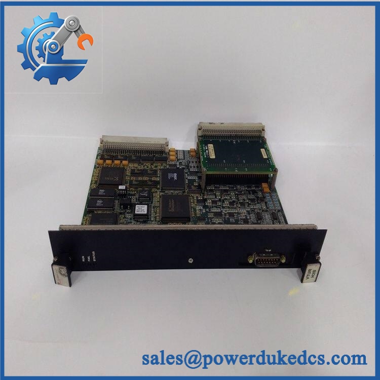
GE IS200VTURH1BAA
Quality Assurance & Testing SOP
Part-number verification: Confirm the physical board marking as . Record all available GE identification, serial number, functional revision, artwork revision, and board labels before testing.
OEM anti-counterfeit visual inspection: Compare PCB construction, component population, connector geometry, board markings, front-panel labeling, and revision identifiers against the approved GE Mark VI reference. Relabeled boards, unexplained PCB rework, inconsistent component placement, or damaged markings require manual review.
Mechanical inspection: Examine the VME edge connectors, 37-pin D-shell interface, captive mounting hardware, PCB surface, and daughterboard connector area for bent contacts, cracking, contamination, corrosion, or evidence of thermal stress.
Connector inspection: Inspect the VME backplane connectors and front-panel J5 interface for oxidation, damaged contacts, loose hardware, or mechanical distortion. Confirm cable identification before installation.
Configuration capture: Retrieve and document the installed VTUR configuration from the approved Mark VI engineering records. Preserve relevant speed-input, synchronizing, protection, and diagnostic settings before replacement.
Power-on self-test (POST): Install the board in an approved Mark VI test rack with the correct supporting hardware. Apply controlled power and verify the actual Status, Fail, and Run LED behavior during initialization. Record every diagnostic indication rather than treating power-up alone as functional acceptance.
MPU signal simulation: Apply calibrated pulse signals to all four speed-input channels. Exercise representative frequencies across the required application range and verify signal recognition, frequency measurement, and stable channel behavior. The GE specification identifies a 2 Hz to 14 kHz input range and 0.05% accuracy.
Low-speed pickup test: Where the test fixture supports it, simulate the low-frequency signal conditions used to verify turning-gear or near-zero-speed detection. Confirm correct signal recognition without introducing false speed indications.
Shaft voltage and current simulation: Apply controlled representative signals to the shaft-voltage and shaft-current monitoring paths. Verify measurement response and diagnostic behavior against the approved test limits.
Synchronizing input test: Simulate generator and bus voltage signals and verify the VTUR input path used by the automatic synchronizing function. Confirm correct signal identification and stable measurements before proceeding to any live breaker-related test.
Trip-interface testing: Using an approved low-energy test fixture, exercise the primary trip command interface to the associated termination board. Verify command generation, feedback monitoring, and diagnostic response without exposing personnel to live turbine trip-solenoid energy.
Flame-detector input test: Where the installed configuration includes flame-detector monitoring, use controlled simulated inputs to verify the corresponding channels and diagnostic response. Do not connect unsupported field sources directly to the test fixture.
I/O load testing: Exercise the relevant simulated speed, voltage, current, trip, and status channels simultaneously. Monitor for intermittent signals, diagnostic instability, processor errors, or communication faults.
TMR verification: For TMR applications, verify the board’s interaction with the corresponding R/S/T protection paths using an approved system-level test procedure. Confirm that voting and diagnostic behavior match the site’s existing architecture.
Final QA release: Record exact model, revision, serial number where available, LED startup result, four-channel MPU test results, shaft-monitoring results, synchronizing test results, trip-interface test, applicable flame-detector test, TMR/simplex verification, technician, and test date. Approved units are packaged using ESD protection and mechanical cushioning.
Procurement & Lifecycle FAQ
Is the genuinely in stock and what is the cutoff for emergency shipping?
Secondary industrial inventory sources continue to list the exact for sale, including new and used inventory categories. Physical quantity varies by supplier, so emergency procurement should confirm the actual unit, exact revision, condition, warehouse location, destination, and carrier cutoff before the PO is released.
How do you verify the condition and authenticity of an obsolete ?
Require physical-unit photographs showing the complete model marking and revision information. The inspection should then cover PCB construction, connectors, VME interfaces, LED indicators, controlled power-up, all four MPU channels, shaft-monitoring paths, and the applicable trip-interface test. The commercial condition should be stated precisely as New Surplus, Tested Surplus, or Tested Refurbished.
Are there any firmware compatibility issues I should warn my engineers about before issuing the PO?
No routine field firmware-flash requirement is identified for the board-level replacement. The key engineering checks are the Mark VI Control System Toolbox configuration, VTUR revision, speed-input setup, termination-board arrangement, synchronizing configuration, and simplex or TMR architecture. GE documentation states that VTUR configuration is handled through the Control System Toolbox.
Is the a direct replacement for an installed board?
An exact can generally be treated as a drop-in replacement at the VME board level when the installed system uses the same board configuration. Engineering must still verify the VTUR revision, connected termination boards, four speed-sensor channels, protection configuration, and overall simplex/TMR architecture before returning the turbine to service.
What warranty and return terms should procurement require?
The PO should specify the exact part number, revision, physical condition, test status, warranty period, DOA definition, return period, and return-freight responsibility. For turbine-protection hardware, retain the actual-unit identification photographs and complete pre-shipment test report as part of the maintenance procurement record.











 Start Chat


