

Description
- Model & Brand: IS215UCVEH2AF | GE General Electric
- Series: Mark VI Speedtronic
- Part Type: UCVE VME Controller / Processor Board
- Functional Designation: UCVEH2
- Primary Application: GE Mark VI turbine control
- Processor: 300 MHz Intel Celeron
- Memory: 32 MB DRAM; 128 KB L2 cache; 8 KB battery-backed SRAM/NVRAM
- Flash Storage: 16 MB or 128 MB CompactFlash, depending on installed configuration
- Physical Dimensions: Approx. 86 W × 162 H mm for the board envelope; complete front-panel/depth dimensions should be checked against the physical unit.
- Estimated Net Weight: Approx. 0.8–0.9 kg
- Estimated Shipping Weight: Approximately 1.3–1.8 kg with ESD protection and rigid packaging
- What’s in the Box: IS215UCVEH2AF controller board; ESD shielding protection; protective packaging; CompactFlash module, cables, rack hardware, and documentation only when specifically included
- Rack Interface: Single-slot VME
- Primary Ethernet: 10BaseT/100BaseTX RJ-45
- Serial Interfaces: COM1 diagnostic; COM2 serial Modbus
- Important Asset Note: CompactFlash capacity and application software should be verified on the actual controller before deployment
Product Introduction
The IS215UCVEH2AF is the processor at the center of a Mark VI control module. GE’s Mark VI system documentation identifies the UCVEH2 as a single-slot controller using a 300 MHz Intel Celeron processor, 32 MB of DRAM, and either 16 MB or 128 MB of flash memory. The controller communicates through a primary 10BaseT/100BaseTX Ethernet interface and two serial ports, with COM1 reserved for diagnostics and COM2 used for serial Modbus communication.
The controller executes application software for steam, gas, land-marine aeroderivative, and balance-of-plant applications, while the VCMI handles data exchange between the VME bus and the control-system database. GE identifies the UCVE as the current single-slot controller generation in the referenced Mark VI system documentation. For replacement work, the physical board alone is not enough: the CompactFlash contents, controller configuration, VCMI type, rack architecture, and application software must all be reconciled (a powered-up spare with the wrong application image can be physically correct yet unusable).
Core Technical Specifications
| Parameter | Value |
|---|---|
| Manufacturer | General Electric |
| Part Number | IS215UCVEH2AF |
| Series | Mark VI Speedtronic |
| Functional Family | UCVEH2 |
| Product Type | VME Controller / Processor Board |
| Architecture | Single-slot VME |
| Processor | Intel Celeron, 300 MHz |
| DRAM | 32 MB |
| L2 Cache | 128 KB |
| Battery-Backed SRAM / NVRAM | 8 KB |
| CompactFlash | 16 MB or 128 MB, configuration dependent |
| Primary Ethernet | 10BaseT/100BaseTX, RJ-45 |
| Ethernet Protocols | TCP/IP, EGD, Ethernet Modbus |
| COM1 | Diagnostic port, 9600 baud, 8-N-1 |
| COM2 | Serial Modbus, 9600 or 19200 baud |
| VME Interface | VME backplane |
| Operating Environment | QNX real-time operating environment in documented Mark VI architecture |
| Control Programming | Control blocks; analog/discrete logic |
| Supported Data Types | Boolean, 16-bit signed, 32-bit signed, 32-bit floating-point, 64-bit long floating-point |
| Power Requirement | +5 VDC, 6 A typical / 8 A maximum |
| Auxiliary +12 VDC | 180 mA typical / 250 mA maximum |
| Auxiliary -12 VDC | 180 mA typical / 250 mA maximum |
| Board Width | Approx. 86 mm |
| Board Height | Approx. 162 mm |
| Mounting | Single-slot Mark VI VME rack |
| Application Software | Site/application dependent |
| Firmware | Controller revision dependent |
| Lifecycle | Legacy Mark VI spare |
GE’s Mark VI system guide specifies the UCVEH2 processor, memory, communications, data types, and power requirements. Supplier records also identify the exact IS215UCVEH2AF as a single-slot Mark VI controller.
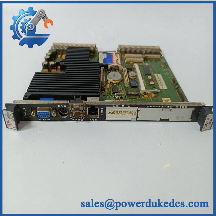
GE IS215UCVEH2AF
🚨 Global Compliance & Industry Certifications
The IS215UCVEH2AF is an internal turbine-control processor. Certification should be recorded against the actual Mark VI control-system configuration rather than assumed from a generic GE listing.
- CE Mark: Mark VI systems can carry applicable European conformity documentation, but no standalone CE declaration specific to was established from the records reviewed.
- UL/cUL: No independent UL/cUL listing specific to this exact controller was established.
- ATEX/IECEx: No standalone ATEX or IECEx certificate specific to was established.
- Marine Approvals: No exact-board DNV, ABS, or Lloyd’s Register approval was established.
- EMC: The complete rack, cabinet, grounding, shielding, and communication installation determine system-level EMC performance.
- Hazardous-Area Use: Do not infer Class I Division 2 or Zone 2 suitability solely from the Mark VI designation.
- System Documentation: Controller hardware, CompactFlash contents, application software, and associated VCMI hardware should remain traceable as one approved system configuration.
Where a Mark VI installation is subject to hazardous-area or site certification, changing the controller without preserving the approved hardware and software configuration can create both operational and compliance issues.
Verify specific lot certifications with OEM.
🚨 Long-Term Storage & Asset Preservation Guide
Protect the CompactFlash and battery-backed memory first. The UCVEH2 architecture uses CompactFlash for system/application storage and battery-backed SRAM for NVRAM functions. Record the CompactFlash capacity and contents before placing the controller into long-term inventory.
Keep the controller inside an ESD shielding bag. Protect the VME connector and front-panel interfaces from dust and mechanical impact. A damaged backplane contact can produce a startup fault that looks like a processor problem.
Control warehouse humidity below approximately 60% RH where practical. Avoid condensation and rapid temperature transitions. Allow the sealed package to acclimate before opening after cold transport or storage.
Monitor the battery-backed memory condition. The UCVEH2 uses 8 KB of battery-backed SRAM/NVRAM, and long-stored controllers should have their battery condition checked before critical deployment. Do not remove or replace a battery without following the applicable GE procedure, because retained configuration may be lost.
Preserve the software image separately from the hardware. Keep a controlled backup of the site’s approved application image and configuration. A controller can pass a hardware POST while still carrying an incorrect application image.
Physical Installation Prerequisites
The is a single-slot VME controller installed in the Mark VI control rack. GE documentation also shows that a control module normally includes the controller together with a VCMI communication board and appropriate cooling provisions.
Before installation:
- Confirm the host system is a GE Mark VI installation.
- Verify the complete part number and revision.
- Confirm the installed system uses the controller architecture.
- Verify the associated VCMI board and its IONet configuration.
- Confirm the VME rack slot and controller orientation before insertion.
- Inspect the VME connector for bent, recessed, oxidized, or contaminated contacts.
- Apply ESD controls before handling the board.
- Verify the rack provides the documented +5 VDC 6 A typical / 8 A maximum requirement and auxiliary ±12 VDC supplies.
- Confirm the cooling fan is operating before starting the controller.
- Preserve the existing Ethernet and COM1/COM2 cable assignments.
- Verify the CompactFlash capacity and approved application image.
- Confirm the controller’s IP configuration before reconnecting Ethernet.
- Preserve cabinet grounding and cable shielding.
- Do not impose an arbitrary 50 mm clearance around the controller. Follow the Mark VI rack’s specified fan and airflow arrangement.
- Confirm that the controller configuration matches the installed VCMI and I/O architecture.
- Perform a controlled power-up and observe Power, Flash, VME SYSFAIL, and communication indicators.
- Check controller diagnostics through the Toolbox environment and COM1 where required.
- Verify the turbine-control application before returning the machine to service.
GE documentation notes that the controller validates its Toolbox configuration against the installed hardware when the rack powers up.
Buyer’s FAQ
Q1. What HS tariff code should be used for GE ?
A: Final classification depends on the importing country’s tariff schedule and the legal description of the controller. Because this is a dedicated industrial computer/controller board, HS heading 8537 or 8538 may be considered depending on how the destination authority treats the complete assembly. The importer or customs broker should confirm the final national tariff code.
Q2. Does Country of Origin mean the country where the controller is shipped from?
A: No. COO is determined under the applicable origin rules for the physical controller, not the export warehouse. Current supplier records identify United States origin for some units. For an audit-ready shipment, retain the actual unit identification and supporting manufacturer or supplier origin documentation.
Q3. How should I package and insure ?
A: Use an ESD shielding bag, rigid protection around the VME connector and front panel, shock-absorbing internal material, and a carton that prevents movement. Current records place the controller around the 0.8–0.9 kg range, while packed weight will be higher. For a turbine-critical controller, shipping insurance should cover the declared replacement value.
Q4. Does include the latest firmware and application software pre-loaded?
A: Do not assume it does. The UCVE controller uses CompactFlash storage for the operating/application environment, and GE documentation identifies application software as specific to the installed turbine-control application. A replacement card should therefore be checked for CompactFlash capacity, approved software image, controller configuration, IP settings, and application compatibility before commissioning.
A: Do not treat live replacement as a routine procedure. The controller is connected directly to the VME backplane and communications architecture. GE’s Mark VI documentation describes dedicated rack installation and cooling requirements rather than universal live-insertion authorization. Follow the site’s approved Mark VI shutdown or controller-replacement procedure, apply ESD controls, verify the software image, and complete controller and turbine-function diagnostics before returning the system to service.











 Start Chat


