

Description
- Brand: General Electric
- Full Model Number: IS215VPROH2BC
- System/Series Family: Mark VI Speedtronic VPRO Turbine Protection
- Core Function: Independent emergency overspeed and turbine trip protection through the VPRO protection architecture
- Top 3 Hardcore Specs: Up to 100 Hz frame rate; MPU sensitivity ≥27 mV peak at 2 Hz; Simplex or TMR system architecture
- Stock Status: New Surplus / Fully Tested Refurbished — exact condition confirmed by available unit
Technical Product Introduction
A failed VPRO board is not an ordinary I/O-card problem. In a Mark VI turbine protection module, the VPRO works with TPRO and TREG hardware to process speed and protection signals and execute emergency trip functions independently of the main turbine control path. The IS215VPROH2BC is identified as a VPRO turbine protection board for emergency overspeed protection, emergency stop functions, backup synchronization-check protection, and associated protection inputs. GE documentation describes three independent VPRO sections in the protection module, allowing the protection architecture to continue operating when one section is removed for maintenance.
The documented VPRO architecture accepts magnetic speed-pickup signals, provides three analog inputs, and monitors nine thermocouple channels primarily for backup exhaust over-temperature protection on gas turbines. Its specified frame rate reaches 100 Hz, while MPU input sensitivity is listed at a minimum of 27 mV peak at 2 Hz; the associated trip-solenoid circuit is specified around a 0.1-second L/R time constant. These figures matter when a replacement is being evaluated against an older protection assembly because signal type, voting architecture, and terminal-board arrangement must remain aligned—not simply the PCB dimensions.
Application Scenarios & Field Realities
- At a gas turbine exhaust protection cabinet, the nine thermocouple inputs can provide backup exhaust over-temperature monitoring. The VPRO architecture distributes these signals across the redundant protection sections, giving the protection system an independent signal path from the main turbine controller.
- When magnetic pickup speed signals are the primary overspeed source, input sensitivity becomes a real commissioning issue. GE documentation specifies MPU inputs for the protection module, so sensor output level, wiring integrity, shielding, and signal frequency should be checked before blaming the replacement board for an unstable speed indication.
- In a turbine emergency-trip cabinet using TREG, the VPRO controls the protection relay logic associated with trip solenoids. The documented architecture uses three voted trip circuits, while the exact number of connected solenoids depends on the terminal-board configuration.
- For an operating turbine requiring maintenance on one protection section, the Mark VI guide specifically describes the three VPRO sections as independent R8, S8, and T8 sections, historically identified as X, Y, and Z. A single section can be powered down and replaced while the turbine continues operating under the remaining protection sections, provided the installed system follows the documented redundant configuration. This is a maintenance procedure, not permission to remove an arbitrary VPRO board under power.
Migration, Compatibility & Installation Traps
Replacement Matrix
| Replacement Scenario | Classification | Engineering Requirement |
|---|---|---|
| IS215VPROH2BC replacing the same VPROH2B configuration | Drop-in Replacement | Confirm exact board identification, revision, terminal-board arrangement, and installed protection configuration |
| Functionally related VPRO revision within the Mark VI family | Software Compatible | Verify firmware level, configuration data, protection-module parameters, and controller diagnostics |
| Replacing H2B with H1B/H3B/H4B/H5B | Hardware Modification Required | Do not substitute solely by physical fit; excitation voltage and TREG architecture must match the application |
The most important distinction is the H-series power and TREG configuration. GE’s Mark VI guide identifies H1B as the standard 125 VDC version and H2B as the 24 VDC version, while H3B, H4B, and H5B are special variants associated with redundant TREG arrangements. A replacement therefore needs to be matched by the installed cabinet architecture, not merely by the “VPRO” functional name.
Field Trap — Voltage Variant: Third-party listings for the exact IS215VPROH2BC assembly sometimes state 125 VDC, while GE’s system guide distinguishes H2B as a 24 VDC application. That discrepancy should be resolved against the actual cabinet wiring, board markings, and protection-module documentation before energization. Do not apply a power source based only on a reseller specification table.
Field Trap — Secondary TREG: The GE guide states that VPROH2B does not support the second TREG board through J4. Systems using a second TREG connected through J4 require the applicable H1A/H1B configuration instead. Check J4 utilization before approving an H2B replacement.
Installation Procedure: Power down the VME I/O processor rack, seat the board using the upper and lower ejector levers, secure the captive front-panel screws, then restore power and inspect the diagnostic indicators. GE also notes that a VPRO firmware update may be required depending on the installed system level.
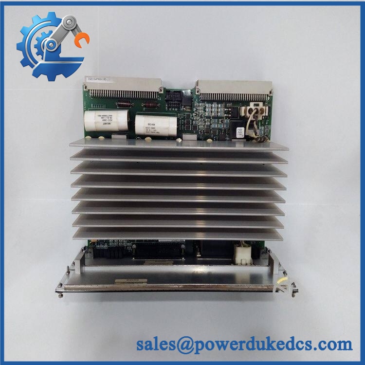
GE IS215VPROH2BC
Quality Assurance SOP
For a surplus IS215VPROH2BC, the acceptance procedure should reproduce the checks that matter in an actual Mark VI protection cabinet. A cosmetic inspection alone is not sufficient.
- OEM anti-counterfeit visual inspection: Verify GE board markings, assembly number, revision identifiers, connectors, PCB construction, and component population against documented VPRO hardware.
- Power-on self-test (POST): Apply the verified cabinet/test voltage and observe initialization behavior, diagnostic indicators, and controller recognition.
- ERR/RUN and status LED verification: Record startup indications and check for abnormal fault states before proceeding to communications testing.
- VPRO diagnostic verification: Confirm that the protection board reports correctly through the applicable Mark VI diagnostic path.
- Communication handshake verification: Test the VPRO Ethernet/IONet communication path where the available test fixture supports it. GE documentation identifies IONet communications between the VPRO protection board and control modules.
- MPU signal simulation: Where test equipment is available, inject controlled magnetic-pickup frequency signals and verify that the board recognizes the expected signal range and protection response.
- Analog and thermocouple input check: Simulate applicable voltage/current and thermocouple inputs to verify channel response and diagnostic behavior.
- Trip logic verification: Test the applicable relay and protection paths using a controlled bench setup without connecting an unverified board directly to a live turbine trip circuit.
- Connector and mechanical inspection: Check J3, J4, J5, J6, J7 and associated locking hardware for bent contacts, looseness, corrosion, or mechanical damage.
- Final traceability record: Capture board identification, revision, test results, visual condition, and pre-shipment photographs for the specific unit being supplied.











 Start Chat


