

Description
- Model: IS220PSVOH1A
- Brand: GE
- Series: Mark VIe / Mark VIeS
- Part Type: PSVO Servo Control I/O Pack
- Core Function: Provides the control-system interface for two servo valve position loops while acquiring LVDT feedback and pulse-rate signals.
- Key Specs: 2 servo valve current outputs; 8 LVDT winding inputs; 2 pulse-rate inputs; nominal 28 VDC pack supply; dual Ethernet interfaces; operating temperature of -30°C to +65°C.
Product Introduction
Inside a GE Mark VIe turbine control architecture, the IS220PSVOH1A sits between the I/O Ethernet network and the TSVCH1A servo terminal board, working with the WSVO servo driver to control two servo valve position loops. Its processor section handles network communication and pack diagnostics, while the dedicated servo circuitry acquires LVDT position feedback and pulse-rate signals.
For a maintenance team supporting an older Mark VIe installation, this distinction matters: the A-revision pack is a legacy spare, not simply another generic analog I/O module. GE documentation identifies IS220PSVOH1B as the later replacement for IS220PSVOH1A, making the A-revision useful primarily where the installed system still requires that exact hardware revision (especially the associated terminal-board arrangement).
The PSVO architecture supports two servo control loops, eight LVDT windings, and two pulse-rate signals. Servo output current is hardware-selected for the connected servo application, so the terminal-board and jumper configuration must be checked before commissioning.
Core Technical Specifications
| Parameter | Value |
|---|---|
| Manufacturer | General Electric (GE) |
| Model | IS220PSVOH1A |
| Product Family | Mark VIe |
| Functional Type | PSVO Servo Control I/O Pack |
| Servo Control Loops | 2 |
| Servo Valve Outputs | 2 servo valve current outputs |
| LVDT Inputs | 8 LVDT windings |
| Pulse-Rate Inputs | 2 |
| Ethernet Interfaces | 2 × RJ45 Ethernet ports |
| Pack Supply Voltage | Nominal 28 VDC |
| Operating Temperature | -30°C to +65°C |
| LVDT Excitation | Generated by the PSVO servo circuitry; nominal excitation frequency is 3.2 kHz |
| A/D Conversion | 16-bit, 100 kHz converter used by the servo board |
| Servo Current Selection | Jumper-selectable output current configuration |
| Maximum Supported Servo Cable Length | Up to 300 m / 984 ft, subject to the documented two-way cable resistance limit |
| Control Architecture | Simplex or TMR applications |
| Associated Servo Driver | WSVO |
| Compatible Terminal Board | TSVCH1A for the H1A version |
| Front Diagnostics | Power, attention, Ethernet, and enable/status indicators |
| Primary Configuration Tool | Control System Toolbox / ToolboxST |
| Board Construction | Conformal-coated electronics |
| Reference OEM Documentation | GEH-6721, Mark VIe Control System Guide |
GE documentation specifies two servo valve current outputs, eight LVDT windings, two pulse-rate inputs, and a nominal 28 VDC supply. The same guide identifies TSVCH1A as the compatible terminal board for PSVOH1A and documents the 3.2 kHz LVDT excitation and 300 m cable capability.
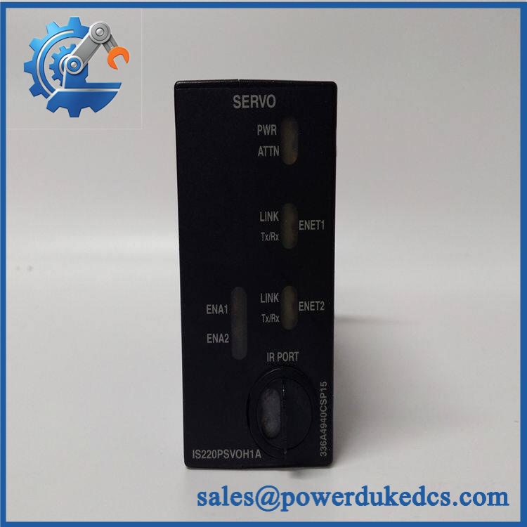
GE IS220PSVOH1A
Application Scenarios & Pain Points
A gas-turbine outage case: A control engineer finds that the servo loop cannot track commanded valve position even though the turbine controller remains online. Once the field wiring and WSVO driver are checked, a PSVO fault becomes a prime replacement candidate. The module processes the LVDT feedback required for closed-loop servo control.
In steam-turbine service, the same architecture can be used for valve position control where accurate hydraulic actuator feedback is required. A degraded LVDT input can produce unstable or invalid position feedback, so checking each feedback channel in ToolboxST is important before condemning the module.
For combined-cycle plants, spare strategy becomes more complicated because the PSVO participates in turbine protection and control loops rather than serving as a general-purpose I/O card. Plants operating with long field cable runs should also verify the documented maximum cable length and resistance limits; GE specifies up to 300 m (984 ft) under defined conditions.
At high-temperature sites, enclosure conditions should be checked against the module’s documented -30°C to +65°C operating range. A pack operating near the upper limit for extended periods deserves closer inspection of temperature diagnostics, connector condition, and cabinet ventilation.
Within a TMR turbine architecture, three PSVO packs can be used, one for each control path. A single failed pack may therefore present differently from a simplex installation, and engineers should review the R/S/T diagnostic state before removing any hardware.
🚨 Common Error Codes & Diagnostic Symptoms
GE’s PSVO documentation uses system diagnostic variables and composite alarms rather than a single universal front-panel numeric fault code. One important composite diagnostic is L#DIAG_PSVO; detailed individual conditions are available through the toolbox diagnostics.
Symptom/Code: L#DIAG_PSVO active → Diagnosis: The PSVO has detected an unhealthy servo current, LVDT feedback, or related terminal-board condition. Check the individual diagnostic bits before replacing hardware. → Action: Isolate the field circuit and associated WSVO/TSVC hardware; replace the PSVO only after external causes are eliminated.
Symptom/Code: Servo current out of limits / not responding → Diagnosis: GE troubleshooting identifies possible open servo-current wiring, incorrect jumper configuration, open servo coil, or PSVO/WSVO hardware failure. → Action: Verify coil resistance, field wiring, jumper settings, and configuration; replace the PSVO and/or WSVO when the hardware fault is confirmed.
Symptom/Code: LVDT regulator feedback out of limits → Diagnosis: The position-feedback signal is outside the expected range, which can result from the sensor circuit, wiring, terminal-board electronics, or PSVO hardware. In systems with redundant sensors, the diagnostic logic can remove a failed sensor from the feedback calculation. → Action: Verify the LVDT circuit and terminal-board signals first; replace the affected module after confirming a pack-level fault.
🚨 Cross-Reference & Lifecycle Migration
Revision Relationship
The most important cross-reference for IS220PSVOH1A is:
IS220PSVOH1A → IS220PSVOH1B
GE lifecycle documentation identifies as the obsolete catalog number and IS220PSVOH1B as the available replacement technology.
This should not be interpreted as an unconditional drop-in replacement in every existing installation. GE’s Mark VIe guide states that PSVOH1A is compatible with TSVCH1A but not with TSVOH1B or the DIN-rail DSVO board. The later H1B version has a different documented accessory combination, so terminal-board revision must be confirmed before ordering a migration spare.
Firmware and Configuration
For migration from the older BPPB technology to BPPC-based I/O, GE documentation lists V04.09.01C as the firmware level associated with the PSVOH1A → PSVOH1B migration. GE also states that automated Auto-Reconfiguration is not supported for this BPPB-to-BPPC migration; the new firmware and configuration must be manually downloaded through ToolboxST.
Therefore, do not order the replacement based on model number alone. Confirm the existing terminal board, ControlST release, I/O pack technology, configuration files, and turbine control topology before scheduling the change.
Lifecycle Status
For a plant still operating this exact configuration, the practical consequence is a higher stock-out and obsolescence risk. Critical turbine servo-loop spares should be handled as controlled buffer inventory rather than treated as routine consumables. A sensible strategy is to retain at least one verified spare for each critical simplex loop, or an engineered quantity consistent with the plant’s TMR architecture and outage strategy.
Field Engineer’s Tech Notes
Warning 1 — Do not ignore the terminal-board revision.
The H1A pack is documented for TSVCH1A. Do not assume that a newer H1B terminal board or another servo terminal assembly has identical electrical and identification behavior. The terminal-board ID is interrogated by the I/O processor, and a mismatch can generate a hardware incompatibility fault.
Warning 2 — Check the servo-current jumpers before blaming the electronics.
A PSVO can appear defective when the real problem is an incorrect current-selection jumper or an open servo circuit. GE specifically lists jumper configuration and field wiring among the troubleshooting checks for servo-current faults. A minute spent verifying those settings can prevent an unnecessary module swap (particularly during an outage).
Strict QA & Testing SOP
For an industrial spare, visual inspection alone is not enough. A controlled QA sequence should be used:
Step 1 — Inbound identity check
Verify the GE part number , revision marking, serial/date-code information, label quality, connector condition, and enclosure condition against the purchase record.
Step 2 — PCB and coating inspection
Inspect the accessible assembly for cracked connectors, contamination, corrosion, abnormal soldering, mechanical damage, and conformal-coating irregularities. Pay particular attention to Ethernet connectors and the terminal-board interface.
Step 3 — Anti-static handling
Handle the module under ESD controls. Use an ESD workstation, wrist strap, conductive packaging, and appropriate protective materials during inspection and packing.
Step 4 — Electrical pre-test
Check power-input continuity and inspect for abnormal resistance or evidence of shorted power circuitry before applying external power. The expected nominal pack supply is 28 VDC.
Step 5 — Live-rig functional test
Where the required Mark VIe test rig and compatible TSVC/WSVO hardware are available, power the pack and verify Ethernet communications, diagnostic indicators, processor operation, servo interface behavior, and relevant LVDT/pulse-rate acquisition functions.
Step 6 — Servo-loop verification
Use an appropriate test configuration to exercise servo output behavior and confirm that feedback diagnostics respond correctly. GE documents manual actuator stroking, position ramping, and step-current methods for evaluating servo performance.
Step 7 — Configuration check
Verify that the tested unit can be identified and configured through the applicable GE Control System Toolbox / ToolboxST environment.
Step 8 — Final inspection and packaging
Photograph the tested serial number, front face, connectors, and overall condition. Place the module in anti-static packaging with mechanical protection suitable for international transport.
Step 9 — Documentation package
Record the inspection result, serial number, test date, test status, and shipping condition. Test videos are available upon request for applicable tested units.
Buyer’s FAQ
Can I hot-swap the while the turbine is operating?
Do not treat the PSVO as universally hot-swappable. The maintenance procedure depends on the specific Mark VIe architecture, simplex/TMR arrangement, terminal board, power configuration, and operating condition. A controlled maintenance procedure should be followed before removing the pack. A PSVO change can affect servo control behavior, so the approved plant procedure takes precedence.
How do I verify that an is New Original?
Start with the physical evidence: GE identification label, part number, revision, serial/date-code consistency, connector construction, PCB assembly quality, and conformal coating. For procurement, ask the supplier for serial-number photographs, inspection records, and test evidence before shipment. No supplier should be accepted solely on a part-number listing.
Is still an actively supported GE spare?
The H1A revision should be treated as obsolete/legacy, while GE’s lifecycle documentation identifies IS220PSVOH1B as the later available replacement technology. That makes H1A inventory more relevant for maintaining an installed base that specifically requires the older hardware arrangement.
What warranty should I expect?
Warranty duration depends on the supplier and the quoted commercial terms. Before issuing the purchase order, obtain the warranty period and coverage in writing, including whether the warranty covers functional failure after installation and what evidence is required for a claim. For critical turbine spares, retaining the serial number and pre-shipment test record is recommended.
Procurement Note
For , the main purchasing risk is not simply availability. The critical questions are H1A versus H1B revision, TSVCH1A versus later terminal-board hardware, BPPB versus BPPC technology, and the installed ControlST/ToolboxST environment. GE’s own documentation confirms the H1A-to-H1B lifecycle transition and the specific terminal-board compatibility constraints.











 Start Chat


