

Description
- Model: IS220PSVOH1B
- Brand: GE
- Series: Mark VIe
- Part Type: Servo Control I/O Pack / Servo Interface, BPPC
- Core Function: Provides the Mark VIe network-to-field interface for turbine servo control, handling 2 servo outputs, 8 LVDT inputs, and 2 pulse-rate inputs.
- Key Specs: Dual 10/100 Ethernet, 28 VDC supply, DC-62 field interface, BPPC processor architecture, and compatibility with GE TSVO/WSVO servo hardware.
- Published Size: Approximately 8.26 × 4.19 × 12.1 cm; one commercial technical record lists 0.5 kg unit weight. Treat those figures as procurement references rather than controlled mechanical-drawing values.
Product Introduction
Inside a Mark VIe turbine cabinet, the IS220PSVOH1B sits between the I/O Ethernet network and the TSVO servo terminal-board assembly. Its field role is specific: it provides the interface for two servo-valve current outputs, eight LVDT feedback channels, and two pulse-rate inputs, while an adjacent WSVO servo-driver assembly handles the servo-valve position loops.
This is the BPPC-based H1B generation, not simply a cosmetic revision of the earlier H1A. GE’s lifecycle notice identifies IS220PSVOH1A as an obsolete catalog number and IS220PSVOH1B as the upgraded available version, making the H1B an important legacy-migration reference for Mark VIe spare planning.
Core Technical Specifications
| Parameter | Value |
|---|---|
| Manufacturer | General Electric |
| Model | IS220PSVOH1B |
| Series | Mark VIe |
| Functional Type | Servo Control I/O Pack |
| Processor Architecture | BPPC |
| Servo Outputs | 2 |
| LVDT Inputs | 8 |
| Pulse-Rate Inputs | 2 |
| External Supply | 28 VDC |
| Certified Supply Range | 27.4–28.6 VDC |
| Maximum Supply Current | 1.0 A DC |
| LVDT Input | 7.14 VAC, 3.2 kHz maximum/rated configuration |
| LVDT Excitation | 6.86–7.14 VAC, nominal 7.00 VAC |
| LVDT Excitation Current | 127 mA AC maximum |
| Servo Output Voltage | -10 to +10 VDC |
| Servo Output Current | -120 to +120 mA DC |
| Speed Input Range | -15 to +15 VDC |
| Speed Sensor Output | 24 VDC, 40 mA |
| Ethernet | 2 independent 10/100 Ethernet ports |
| Ethernet Connector | RJ45 |
| Field Interface | DC-62 |
| LVDT Resolution | 14-bit |
| Pulse-Rate Resolution | 16-bit |
| Servo Output Resolution | 12-bit |
| Operating Ambient | -40°C to +70°C in the applicable GE hazardous-location documentation |
| Approx. Dimensions | 8.26 × 4.19 × 12.1 cm |
| Approx. Unit Weight | 0.5 kg reported commercially |
The electrical ratings above are supported by GE’s Mark VIe hazardous-location documentation, including the 28 VDC / 1 A supply limit, LVDT excitation characteristics, speed-input range, and ±120 mA servo-output range.
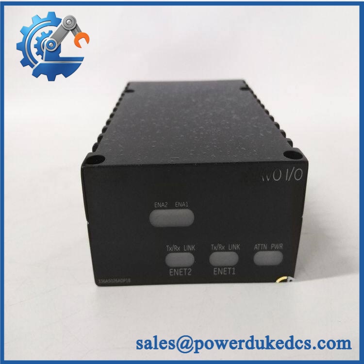
GE IS220PSVOH1B
Application Scenarios & Pain Points
A turbine actuator starts drifting during load changes, even though Ethernet communication remains normal. In this situation, the PSVO is worth checking alongside the WSVO driver and LVDT feedback loop; a healthy network link does not prove the servo feedback chain is healthy.
For gas-turbine fuel and control-valve applications, the module provides the field interface for two servo position loops, with LVDT feedback used for position measurement. GE’s architecture calls for the associated TSVO terminal board and WSVO servo-driver hardware.
At an installation running in a hot turbine-control cabinet, thermal margin becomes important. The applicable Mark VIe hazardous-location documentation permits an ambient range reaching 70°C, but cabinet airflow and nearby heat sources still need to be assessed during replacement planning.
With vs. without a controlled spare: without a verified H1B spare, a failed servo-interface pack can turn a straightforward electronics replacement into a longer turbine outage while the plant searches for the correct revision, terminal-board combination, and software baseline.
During legacy Mark VIe migration, the H1B is particularly useful because GE’s lifecycle notice identifies it as the upgraded counterpart to the obsolete IS220PSVOH1A.
Common Error Codes & Diagnostic Symptoms
Symptom/Code: PSVO hardware ID mismatch / terminal-board compatibility diagnostic
→ Diagnosis: The I/O pack detects an incompatible or incorrectly identified terminal-board/acquisition arrangement. GE’s Mark VIe architecture uses electronic identification to validate connected hardware.
→ Action: Verify the complete PSVO, TSVO, WSVO, and internal-board configuration before replacing the pack.
Symptom/Code: ENET1/ENET2 communication fault or loss of I/O network status
→ Diagnosis: A failed Ethernet path, power problem, processor fault, connector issue, or I/O pack failure can prevent normal network communication. Front-panel network LEDs are useful for separating network faults from deeper module faults.
→ Action: Check both RJ45 paths, 28 VDC supply, LED state, and controller diagnostics; replace the I/O pack when the module itself fails the approved diagnostic procedure.
Symptom/Code: Abnormal actuator position / LVDT feedback instability
→ Diagnosis: A drifting or frozen actuator indication can originate in the LVDT circuit, terminal board, servo driver, wiring, or PSVO acquisition electronics. The PSVO alone should not be condemned from a single bad trend.
→ Action: Isolate the LVDT loop and servo-driver chain first; replace the PSVO when board-level diagnostics or substitution testing confirms the module fault.
GE public documentation does not establish a single universal numeric fault-code list for every PSVO installation. The exact diagnostic text and code can vary with the ControlST configuration and system generation, so numeric codes should be taken from the site’s approved alarm database rather than invented from a generic spare-parts listing.
Cross-Reference & Lifecycle Migration
Revision and Replacement Path
GE’s lifecycle documentation is clear on the most important relationship:
IS220PSVOH1A → IS220PSVOH1B
The H1A was identified as the obsolete catalog number, while the H1B was introduced as the upgraded technology version. GE’s notice also states that upgraded Mark VIe I/O packs were designed to be backward-compatible with older technology, including mixed technology configurations, subject to the applicable system requirements.
Important Hardware Compatibility
The PSVOH1B is not a generic stand-alone servo card. GE’s certification documentation identifies approved combinations including:
- IS220PSVOH1B + IS200TSVCH2A + IS410WSVOH1A
- A RoHS-compliant configuration using + IS400BSVOH1A + IS200TSVCH2A + IS410WSVOH1A.
That means a buyer should verify the complete hardware chain rather than treating the H1B suffix as sufficient compatibility evidence.
Firmware / Software Migration
The H1B uses the BPPC platform. GE-related replacement guidance identifies a BPPC I/O upgrade requirement for systems on older ControlST releases; one published procedure specifically calls for BPPC I/O Upgrade V05.01.03 when upgrading from older ControlST environments. This is a site-specific engineering task, not a universal firmware requirement for every H1B replacement.
Lifecycle Status
Lifecycle classification: Upgraded / replacement generation; not the obsolete H1A.
For buffer-stock strategy, treat the H1B as the preferred warehouse reference for sites still operating Mark VIe systems, but verify current OEM support and site software compatibility before purchasing large quantities. The public GE lifecycle notice establishes the H1B as the upgraded successor in the H1A/H1B transition; it does not by itself prove unrestricted current OEM availability in 2026.
Field Engineer’s Tech Notes
Warning 1 — Do not condemn the PSVO from an actuator-position fault alone.
A junior engineer sees unstable LVDT feedback and immediately swaps the I/O pack. That is risky. Check the LVDT wiring, terminal-board connections, WSVO driver, excitation, and feedback trend first. The PSVO is one element in the complete servo loop.
Warning 2 — Verify the terminal-board and driver combination before installation.
The mechanical package can look correct while the certified electrical architecture is wrong. GE’s documentation ties the H1B to specific TSVO and WSVO combinations, including distinct RoHS hardware arrangements.
Also remember the ESD risk. Handle the pack by its approved edges and connector hardware; do not place fingers across exposed circuitry or connector contacts during warehouse inspection.
Strict QA & Testing SOP
Step 1 — Inbound identity inspection
Record the complete marking, serial number, revision information, date code where present, and country-of-origin documentation. Photograph the nameplate before the unit enters controlled inventory.
Step 2 — Physical inspection
Check the housing, mounting bracket, RJ45 ports, DC-62 connector, LEDs, and PCB condition. Look specifically for cracked plastics, bent connector contacts, corrosion, contamination, and evidence of improper previous installation.
Step 3 — ESD-controlled preparation
Move the module to an ESD-controlled bench. Retain the original static-protective packaging for final dispatch.
Step 4 — Electrical verification
Apply the controlled 28 VDC supply and verify that the current draw stays within the approved test-rig limit. Confirm startup behavior and front-panel diagnostic indications. GE’s certified maximum supply current is 1 A for the specified system arrangement.
Step 5 — Communication test
Connect the module to an approved Mark VIe-compatible test environment and verify both Ethernet paths, processor startup, and communication diagnostics.
Step 6 — Servo-interface test
Where the test facility supports it, verify representative LVDT acquisition, pulse-rate input handling, and servo-output response. Confirm signal polarity, scaling, and stability rather than merely checking that the module powers up.
Step 7 — Configuration verification
Check the ControlST/ToolboxST environment and confirm the expected hardware identification and software compatibility before the board is released as a ready-to-install spare.
Step 8 — Final QA and packaging
Attach a QC record, preserve photographs and test results, place the unit in ESD-safe packaging, add cushioning, and use a moisture-controlled outer carton. Test videos are available with the inspection record when requested for procurement or audit review.
Buyer’s FAQ
Q: Can I hot-swap an while the turbine is operating?
A: Do not treat it as a routine hot-swap device. The PSVO participates in a servo-control loop, and removal can affect control availability, diagnostics, or the actuator path. Follow the site’s GE-approved maintenance procedure and determine whether the architecture provides sufficient redundancy before removing the pack.
Q: How do I know a “New Original” is actually authentic?
A: Request the physical nameplate photograph, complete part number, serial number, hardware revision, factory packaging evidence, and traceability documents. A sealed box alone does not prove provenance. For regulated procurement, match the physical markings against the purchase specification before accepting the asset.
Q: Does replace IS220PSVOH1A directly?
A: GE’s lifecycle notice identifies as the upgraded available counterpart to obsolete IS220PSVOH1A. Even so, verify the ControlST version, terminal-board/servo-driver combination, and site configuration before declaring the replacement a field-ready drop-in.
Q: What warranty should I require on a replacement unit?
A: Put the warranty period and failure-return procedure directly into the purchase order. For a turbine-control spare, require coverage against DOA and functional failure after installation, with serial-number traceability and a defined replacement or repair process. A generic “tested” statement is not a substitute for written warranty terms.











 Start Chat


