

Description
- Model: IS220YAICS1A L
- Brand: GE General Electric
- Series: Mark VIeS Functional Safety System
- Part Type: Safety Analog Input/Output I/O Pack
- Core Function: Provides the field-facing analog interface between process transmitters/actuators and Mark VIeS safety control logic. GE identifies the YAIC family as a safety analog I/O platform.
- Key Specs: 10 analog inputs, up to 4 analog outputs reported for the IS220YAICS1A revision, 28 VDC nominal supply, 27.4–28.6 VDC operating range, and maximum current draw of approximately 0.49 A.
- Field Interface: Used with specified STAI/TBAI terminal-board families; the terminal board is part of the functional configuration, not merely a mounting accessory.
Product Introduction
A safety-system analog channel cannot be treated like an ordinary PLC analog card. In a turbine or process shutdown application, loss of a transmitter signal, an incorrect scaling configuration, or an incompatible I/O revision can affect the integrity of the protective function. The GE IS220YAICS1A L belongs to the Mark VIeS safety analog I/O family and interfaces process analog sensors and actuators with the Mark VIeS safety control logic. GE describes the YAIC architecture as supporting 10 analog inputs and analog outputs in the applicable safety configuration.
The hardware sits at the distributed I/O layer rather than in the main controller chassis. Its electrical interface is based around a 28 VDC nominal supply, with a published 27.4–28.6 VDC range and approximately 0.49 A maximum current for this YAIC revision. The supplied suffix “L” should remain in your inventory record exactly as marked; it should not be assumed to represent a different GE catalog revision without checking the physical nameplate and controlled documentation.
Core Technical Specifications
| Parameter | Value |
|---|---|
| Manufacturer | GE General Electric |
| Model | IS220YAICS1A |
| Inventory Marking | IS220YAICS1A L |
| Product Family | Mark VIeS Safety Analog I/O |
| Part Type | Safety Analog I/O Pack |
| Analog Inputs | 10 |
| Inputs 1–8 | Configurable voltage/current inputs |
| Inputs 9–10 | Current-input channels |
| Input Voltage Range | -10 to +10 VDC on applicable channels |
| Input Current Range | 0–20 mA on configurable channels |
| Analog Outputs | Up to 4 reported for this hardware revision |
| Analog Output Voltage | 0–16.3 VDC |
| Analog Output Current | 0–20 mA |
| Transmitter Supply | 24.0 VDC nominal |
| Transmitter Supply Range | 22.8–25.2 VDC |
| Transmitter Supply Current | Up to 21 mA |
| Module Supply | 28.0 VDC nominal |
| Supply Range | 27.4–28.6 VDC |
| Maximum Supply Current | 0.49 A DC |
| Approx. Maximum Electrical Input | 13.7 W at 28 V and 0.49 A |
| Network | Dedicated Mark VIeS I/O network |
| Terminal-Board Families | STAI/TBAI families specified for YAIC applications |
| Safety Architecture | Simplex and TMR configurations within Mark VIeS architecture |
| Hazardous-Location Use | Applicable certified configurations |
| Operating Environment | Follow the exact Mark VIeS installation/certification limits for the revision |
| Memory | Firmware/storage capacity is revision-dependent and should be verified from the physical unit |
The 0.49 A maximum current deserves attention in cabinet heat calculations. At 28 VDC, the corresponding upper electrical input is about 13.7 W; actual heat dissipation will vary with operating condition, field loading, and the complete terminal-board configuration. The published YAIC electrical ratings specify the 28 VDC supply and analog signal ranges shown above.
One correction is worth emphasizing for buyers: GE’s current Mark VIeS functional-safety documentation identifies the IS420YAICS1B as the common safety analog I/O pack for the newer documented system generation, while older documentation and commercial records identify IS220YAICS1A. That makes revision and system-generation verification essential before treating a newer YAIC as a drop-in replacement.
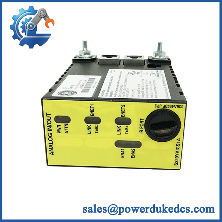
GE IS220YAICS1A L
Application Scenarios & Pain Points
In a gas-turbine installation, a YAIC channel can sit between pressure, temperature, or process transmitters and the safety logic. With cabinet ambient temperatures reaching 50°C or higher, supply voltage and cabinet thermal conditions should be checked rather than assumed from nominal specifications.
For steam-turbine protection, multiple analog measurements may participate in permissive, shutdown, or limiting functions. The key issue becomes channel integrity: a physically interchangeable analog pack is not necessarily configuration-compatible with the existing terminal board or safety application.
Oil and gas process facilities commonly impose hazardous-area requirements on distributed I/O. In those installations, the correct certified pack/terminal-board combination matters just as much as the signal range because field wiring enters an electrically classified environment.
Without the correct STAI/TBAI terminal-board arrangement, the I/O pack cannot simply be treated as an independent replacement part. GE’s functional-safety documentation specifically defines the terminal boards as part of the analog I/O module configuration.
During legacy migration, the practical pain point is traceability. Record the old module’s hardware revision, terminal board, firmware, and application configuration before changing to another YAIC generation; otherwise a spare that passes a bench power-up test can still fail during system integration.
🚨 Common Error Codes & Diagnostic Symptoms
Symptom: I/O Pack Diagnostic or Network Fault → Diagnosis: Loss of communication with the Mark VIeS I/O network can result from module electronics, Ethernet/I/O-network wiring, power loss, or configuration mismatch. → Action: Verify the 28 VDC supply, network connections, diagnostics, and configuration; replace the I/O pack when hardware failure is confirmed.
Symptom: Analog Channel Out-of-Range / Bad Quality → Diagnosis: An individual channel may show an open field loop, incorrect signal scaling, terminal-board mismatch, wiring fault, or damaged input circuitry. → Action: Simulate the input at the terminal board and compare measured response with the expected engineering range; replace the module if the channel electronics fail the controlled test.
Symptom: Multiple Analog Channels Fail Simultaneously → Diagnosis: A common supply, terminal-board, network, or I/O-pack fault becomes more likely than simultaneous transmitter failure. → Action: Check module power and terminal-board identification first, then replace the pack if the fault follows the hardware.
Specific GE diagnostic identifiers can vary with the Mark VIeS controller firmware and ToolboxST configuration. Do not assign a generic “error code” to this module without the system diagnostic record.
🚨 Cross-Reference & Lifecycle Migration
The belongs to an earlier Mark VIeS safety-I/O generation. GE’s current functional-safety documentation describes IS420YAICS1B as the common YAIC safety analog I/O pack for the documented newer architecture, while the older remains identified in earlier hazardous-location and product documentation.
That does not establish unconditional interchangeability.
The terminal-board family must match. Firmware and safety-system configuration must also be validated. GE’s documentation describes specific STAI/TBAI board combinations and different Simplex/TMR arrangements, so migration should be handled as an engineering change rather than a simple warehouse substitution.
Lifecycle status: Limited / Legacy. Treat this as a strategic spare where the installed Mark VIeS asset base still depends on the IS220 generation. For critical sites, maintain at least one verified replacement and preserve the associated terminal-board and firmware compatibility record.
A firmware flash may be required when moving between hardware revisions or approved system releases, but never overwrite existing firmware solely because a newer image is available. Match the software baseline to the target safety application.
Field Engineer’s Tech Notes
First warning: verify the terminal board before installing the pack. YAIC is not a universal analog I/O device. The STAI/TBAI board determines the field interface, wiring arrangement, and applicable redundancy configuration (a connector that physically mates is not sufficient evidence of compatibility).
Second warning: don’t power it from an assumed 24 VDC cabinet rail. This revision is specified around 28 VDC, with a published operating range of 27.4–28.6 VDC. Measure voltage at the I/O pack under load before commissioning.
Handle the PCB under ESD controls. Analog input circuitry can survive a casual visual inspection yet exhibit unstable readings after an electrostatic event.
Strict QA & Testing SOP
Step 1 — Inbound inspection. Record model, suffix, serial number, hardware revision, date code, terminal-board compatibility, physical condition, connector condition, and packaging status. Photograph the identification labels.
Step 2 — ESD-controlled bench preparation. Keep the module inside an antistatic workstation and use grounded wrist/bench protection. Inspect the housing, connector pins, mounting points, and board surfaces under suitable lighting.
Step 3 — Electrical verification. Apply a controlled 28 VDC supply within the specified range. Monitor input current during startup and verify that no abnormal heating develops around power-conditioning components.
Step 4 — Network test. Connect the pack to an approved Mark VIeS test environment and verify network communications, module identification, diagnostics, and controller recognition.
Step 5 — Analog I/O simulation. Inject controlled voltage/current signals across the applicable input channels. Verify scaling, channel response, transmitter-power behavior, output response, and diagnostic quality flags against the approved test procedure.
Step 6 — Firmware/configuration verification. Record the installed firmware and configuration revision; compare them with the intended target system before approving the asset for field deployment.
Step 7 — Final QC. Record test results, inspector/date, serial number, and pass/fail status. Return the module to an ESD shielding bag with connector protection and impact-resistant packaging.
Test videos are available for procurement and QC records when the inventory lot requires documented functional verification.
Buyer’s FAQ
Do not assume that it is safe. Removal or insertion should follow the approved Mark VIeS maintenance procedure, because power, network state, safety redundancy, and process consequences all matter. A live replacement can create an unexpected I/O or safety-system state.
How do I know a “New Original” unit is authentic?
Check the GE identification label, complete part number, serial number, PCB markings, date code, connector condition, and physical construction. Factory packaging alone is not enough; perform incoming inspection and retain photographs and test records.
What warranty should I expect?
Warranty depends on the actual supply source and condition classification. For New Original, New Surplus, and Refurbished inventory, the warranty terms should be stated explicitly on the quotation and purchase order rather than assumed from the GE brand.
Does the unit come with the latest firmware?
Not automatically. Firmware must correspond to the target Mark VIeS safety configuration and hardware revision. Record the installed firmware before shipment and verify compatibility before commissioning; the newest available image is not necessarily the correct image for a legacy controller.











 Start Chat


