

Description
- Model: IS230STAOH2A
- Brand: GE General Electric / GE Energy
- Series: Mark VIe and Mark VIeS control systems
- Part Type: STAOH2A analog output terminal module
- Core Function: Provides the physical field termination and signal interface for a PAOC analog output I/O pack, converting controller commands into analog output signals for valves, actuators, drives, and other process equipment.
- Key Specs: 16 analog outputs, 0–20 mA, removable 36-terminal Euro-style block, simplex PAOC architecture, and bracket-assisted DIN-rail mounting.
- Architecture Note: The IS230STAOH2A is an assembly built around the IS200STAO terminal board and PAOC I/O pack; do not confuse it with the PAOC electronics alone.
Product Introduction
When an analog actuator refuses to respond, the fault is not always inside the controller. A loose terminal connection, an incorrect I/O pack pairing, or a failed output interface can leave a healthy control processor looking guilty. The GE IS230STAOH2A belongs to the Mark VIe distributed-I/O layer and provides the analog output field interface for a PAOC I/O pack, with the terminal board handling field wiring and output conditioning before signals reach the connected equipment.
From a maintenance perspective, the removable terminal block is an important distinction. The STAOH2A uses a 36-position high-density Euro-style terminal block, supports 16 analog output channels rated 0–20 mA, and incorporates noise-suppression circuitry to reduce the effect of surge and high-frequency interference (particularly useful around motor control and other inductive equipment). It is a simplex assembly, so the replacement strategy differs from a TMR analog-output architecture.
Core Technical Specifications
| Parameter | Value |
|---|---|
| Manufacturer | GE General Electric / GE Energy |
| Model | IS230STAOH2A |
| Product Family | Mark VIe / Mark VIeS |
| Part Type | Analog Output Module |
| Terminal Board | IS200STAO |
| I/O Pack | PAOC |
| Redundancy | Simplex |
| Analog Output Channels | 16 |
| Output Signal | 0–20 mA |
| Terminal Block | 36-terminal high-density Euro-style |
| Terminal Block | Removable |
| Mounting | Bracket-assisted DIN rail |
| Board Identification | On-board ID chip |
| Signal Protection | Noise suppression and surge filtering |
| Primary Application | Analog command output to process devices |
| Typical Loads | Valves, actuators, drives, instrumentation |
| Terminal Board Size | Approximately 15.9 cm H × 10.2 cm W |
| Cabinet Mounting | DIN-rail distributed I/O |
| Heat Dissipation | Generated by the PAOC electronics and output circuitry; calculate cabinet heat from the installed I/O-pack configuration |
| Memory | No independent application-memory specification should be assigned to the terminal module; memory resides in the associated I/O-pack electronics |
The 36-terminal removable block is especially relevant during field replacement. GE’s Mark VIe documentation identifies the STAOH2A as a removable-terminal configuration, while the STAOH1A uses a non-removable terminal arrangement.
The module should not be represented as a generic “16-channel analog card.” Its function depends on the PAOC pack, the terminal-board identification chip, cabinet wiring, and the Mark VIe I/O configuration. A replacement assembly must therefore be checked as a complete I/O node rather than by channel count alone.
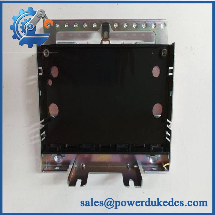
- GE IS230STAOH2A
Application Scenarios & Pain Points
A gas-turbine plant may use the STAOH2A to drive analog control devices such as valve positioners and other final-control elements. With cabinet temperatures approaching 50°C+, output accuracy, connector integrity, and airflow deserve inspection before blaming the connected actuator.
For steam-turbine auxiliary systems, a damaged analog-output interface can present as a controller-command problem even when the upstream logic is correct. The practical troubleshooting point is to verify the output at the terminal block before replacing higher-level hardware.
In oil and gas facilities, long field cable runs can expose analog outputs to electrical noise. The STAOH2A’s documented filtering and surge-suppression circuitry provides a hardware layer against high-frequency interference, but wiring separation and proper shield termination remain necessary.
With vs. without the correct terminal-board configuration: with STAOH2A, the PAOC pack has the intended 16-channel field termination and removable connection hardware; without the correct STAOH/PAOC pairing, the I/O node can be physically installed yet remain electrically or diagnostically incompatible.
During legacy migration, the removable terminal block can reduce rewiring effort, but the engineer still needs to verify point mapping, output scaling, and the exact PAOC hardware revision before changing the installed node.
🚨 Common Error Codes & Diagnostic Symptoms
Symptom: Output channel reads 0 mA despite a valid controller command → Diagnosis: Check terminal seating, field wiring, PAOC pack connection, output protection circuitry, and channel hardware. → Action: Verify the output directly at the terminal interface; replace the module or associated PAOC pack when the fault follows the hardware.
Symptom: One output is unstable or noisy → Diagnosis: High-frequency interference, poor shielding/grounding, damaged output circuitry, or a loose removable terminal can produce an unstable current signal. → Action: Check wiring segregation and terminal torque first; replace the defective hardware if the channel fails a controlled loop test.
Symptom: Multiple analog outputs fail together → Diagnosis: A common PAOC/I/O-pack power or interface issue is more likely than simultaneous field-device failures. → Action: Verify module supply, I/O-pack diagnostics, terminal-board ID, and network status before replacing individual field devices.
Exact Mark VIe diagnostic text varies with controller firmware and the installed ToolboxST configuration. Use the system event log rather than assigning an arbitrary universal fault code.
🚨 Cross-Reference & Lifecycle Migration
The IS230STAOH2A is an terminal-module assembly, not merely a terminal board catalog number. Secondary technical documentation identifies its internal combination as an IS200STAO terminal board plus a PAOC I/O pack.
A particularly important cross-check is the STAOH1A versus distinction. GE’s Mark VIe documentation identifies STAOH1A as a non-removable terminal configuration and as removable. Do not substitute one for the other purely because the output channel count appears equivalent. (turn936557search4)
Lifecycle status: Limited / Legacy. Treat this assembly as a strategic spare where installed Mark VIe systems still depend on the architecture. Maintain verified stock when an outage would otherwise require field rewiring or an obsolete-system retrofit.
Firmware normally resides in the associated PAOC I/O pack, not in the passive terminal-board portion itself. A firmware update may therefore be relevant when the complete I/O pack is replaced, while the terminal board alone generally does not require “flashing.” Always compare the existing PAOC revision and system configuration before commissioning.
Field Engineer’s Tech Notes
First warning: do not mix terminal-board identity with I/O-pack identity. The IS200STAO board contains an identification device used by the I/O pack for system diagnostics. If that identity does not correspond to the expected configuration, the node can generate faults even though the wiring appears correct.
Second warning: the removable terminal block is an asset, not packaging hardware. Before replacing the module, photograph terminal positions and wire labels, then verify every point against the approved drawing. One misplaced analog-return conductor can create a difficult-to-trace control problem after an otherwise clean installation.
Use ESD controls whenever the PAOC pack is removed. Protect the exposed connector from dust and accidental contact while the terminal assembly remains energized.
Strict QA & Testing SOP
Step 1 — Inbound inspection. Confirm , terminal-board revision, PAOC pack identity, serial number, labels, physical condition, mounting hardware, and removable terminal block. Photograph all identification markings.
Step 2 — Mechanical inspection. Check the DIN-rail bracket, retaining hardware, terminal-block latch, terminal screws, connector pins, and PCB condition. Look for discoloration or signs of previous overheating.
Step 3 — Electrical inspection. Verify supply requirements for the installed PAOC configuration and inspect for abnormal resistance, damaged protection components, or evidence of field overvoltage. Do not apply uncontrolled bench power.
Step 4 — Live rig testing. Install the assembly on an approved GE Mark VIe test setup with the correct PAOC configuration. Confirm I/O-pack recognition, terminal-board identification, diagnostics, and communications.
Step 5 — Analog output test. Command each channel through its approved test range and measure the resulting current at the field interface. Verify 0–20 mA behavior, channel isolation as applicable, output stability, and fault reporting.
Step 6 — Configuration check. Compare point assignments, scaling, engineering units, and I/O configuration with the intended plant database. Record PAOC firmware revision where applicable.
Step 7 — Final QC and packaging. Mark the inspection result, retain the test record, reinstall protective covers, place the assembly in an ESD-shielding bag, and use rigid cushioning for shipment.
Test videos are available for the live-rig verification stage when a procurement package requires visual evidence of functional testing.
Buyer’s FAQ
Do not assume it is safe to remove or insert the assembly under power. The PAOC pack and terminal-board interface are part of an energized distributed-I/O circuit; follow the approved Mark VIe maintenance procedure and assess the process consequence before intervention.
How do I verify a New Original unit?
Check the GE identification markings, terminal-board revision, PAOC pack identity, physical construction, terminal block condition, and serial/date information. For a high-value purchase, request photographs before shipment and retain the incoming QC record.
What warranty should be on the purchase order?
Specify the warranty in writing and tie it to the exact assembly and its stated condition—New Original, New Surplus, or Refurbished. Avoid accepting a generic warranty statement that does not define coverage for functional failure after installation.
Does this module arrive with the latest firmware pre-loaded?
The terminal board itself is not the firmware-bearing component. Firmware is associated with the PAOC I/O pack, so any firmware requirement must be checked against the complete I/O-node configuration before commssioning.











 Start Chat


