

Description
- Model: GE IS230TBAIH2C
- Brand: General Electric
- Series: Mark VI / Mark VIe turbine control family
- Part Type: TBAI Analog I/O Terminal Board
- Core Function: Provides field termination, analog signal conditioning, transmitter power, and signal fan-out between field devices and compatible GE I/O processors.
- Key Specs: 10 analog inputs + 2 analog outputs, three DC-37 processor interfaces, simplex or TMR architecture, configurable current/voltage inputs, 24 VDC transmitter supply, and 0–20 mA / 0–200 mA output capability.
Product Introduction
The GE IS230TBAIH2C is installed at the physical field-wiring boundary of a GE Mark VI turbine control system. It is a TBAI analog I/O terminal board, not a processor or independent I/O pack. The board accepts ten analog input channels and provides two analog output channels, while its three DC-37 interfaces allow the same terminal-board design to support simplex and TMR configurations.
Field deployments typically use this assembly with transmitters, valve positioners, and other analog instrumentation where clean termination and predictable signal routing are essential. The board supports two-, three-, and four-wire transmitters as well as externally powered devices (the exact loop arrangement must follow the application wiring documentation). Its revision H2C should be checked against the installed processor and terminal-board architecture before procurement.
Core Technical Specifications
| Parameter | Value |
|---|---|
| Manufacturer | GE General Electric |
| Model | IS230TBAIH2C |
| Series | Mark VI / Mark VIe |
| Functional Acronym | TBAI |
| Product Type | Analog I/O Terminal Board |
| Analog Inputs | 10 channels |
| Analog Outputs | 2 channels |
| Input Signal Type | Current or voltage, jumper-configurable |
| Typical Input Range | 1–5 VDC; current-loop configurations supported |
| Current Input Configuration | Jumper-selectable current input arrangements |
| Analog Output | 0–20 mA |
| High-Current Output Configuration | 0–200 mA |
| Transmitter Supply | 24 VDC |
| Transmitter Supply Capability | Approximately 21 mA continuous per output |
| Short-Circuit Protection | Provided for applicable transmitter-supply outputs |
| Maximum Lead Resistance | Approximately 15 Ω for specified input-loop conditions |
| Analog Output Load | Up to approximately 500 Ω, application dependent |
| Processor Interfaces | 3 × DC-37 connectors |
| Simplex Connection | JR1 |
| TMR Connections | JR1, JS1, JT1 |
| Supported Architecture | Simplex and TMR |
| Primary Processor Association | GE VAIC I/O processor architecture |
| Field Terminal Blocks | 2 |
| Terminals per Block | 24 |
| Maximum Wire Size | Up to approximately #12 AWG |
| Shield Termination | Dedicated shield connection points |
| Noise Protection | Input/output surge and high-frequency noise suppression |
| Configuration | Hardware jumpers |
| Board Dimensions | Approx. 101.6 × 330.2 mm |
| Operating Temperature | Approximately -30°C to +65°C |
| Firmware | None on the terminal board itself |
| Hot Swap | Do not assume live replacement |
Configuration details
The board uses physical jumpers to establish the required analog configuration. J1A–J8A select the current-versus-voltage arrangement for the corresponding input channels, while the associated J1B–J8B positions determine the applicable return connection.
Inputs 9 and 10 have separate jumper arrangements for their current range and return configuration. Output current selection is also hardware-configured, including the 0–20 mA / high-current output arrangement.
That means an electrically healthy replacement can still behave incorrectly when the jumper pattern does not match the original board. Photograph the existing configuration before removal.
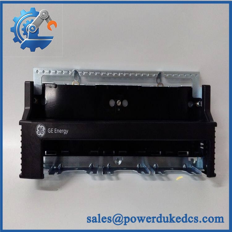
GE IS230TBAIH2C
Application Scenarios & Pain Points
Gas turbine fuel and valve control: A TBAI board may receive transmitter signals for pressure, temperature, or flow while simultaneously driving current-controlled field devices. The combination of 10 inputs and 2 outputs makes it suitable for compact analog control loops.
Compressor and anti-surge systems: Fast-changing analog measurements can pass through the TBAI field interface before reaching the associated processor. Noise suppression and proper shield termination become particularly important around motor and drive equipment.
Steam turbine auxiliary systems: Two-wire and externally powered transmitters can be landed at the terminal blocks while the processor-side connectors provide the required architecture for signal acquisition.
TMR turbine control: In a TMR installation, the three DC-37 connectors provide the R, S, and T processor paths. A single terminal board therefore supports signal fan-out to multiple redundant I/O processors rather than simply serving one controller.
Brownfield maintenance: In a cabinet operating at 50°C+ ambient, technicians should inspect terminal connections, board contamination, and cabinet airflow before blaming an analog channel fault on the TBAI hardware.
🚨 Common Error Codes & Diagnostic Symptoms
Symptom/Code: One analog input remains fixed despite a known-good transmitter
→ Diagnosis: Possible jumper misconfiguration, open field wiring, excessive lead resistance, failed input-conditioning components, or an incorrect processor-side connection.
→ Action: Verify loop current/voltage at the terminals first, then confirm the corresponding JxA/JxB configuration and DC-37 connection; replace the board after controlled testing confirms a hardware fault.
Symptom/Code: Analog output fails to reach commanded current
→ Diagnosis: Output-load resistance, jumper configuration, wiring, or an output-driver fault can produce this condition. A defective output may also trigger the associated I/O diagnostic.
→ Action: Measure the output under a controlled load, verify the output-selection jumper, and replace the terminal board when the board-level output test fails.
Symptom/Code: Multiple channels affected in TMR architecture
→ Diagnosis: A shared terminal-board supply, common wiring point, connector problem, or board-level fault may affect several channels simultaneously.
→ Action: Compare R/S/T paths and inspect all three DC-37 connections before replacing processors.
Exact controller diagnostic codes vary with the Mark VI software and processor configuration; the terminal board itself does not provide a universal standalone error-code set.
🚨 Cross-Reference & Lifecycle Migration
Lifecycle Status: Legacy / Obsolescence-Controlled Spare
The IS230TBAIH2C belongs to the legacy GE Speedtronic Mark VI analog terminal-board family. Public industrial records identify the unit as a TBAI terminal board used with VAIC processors, while newer Mark VIe architectures can use different terminal-board and I/O-pack arrangements.
Compatibility considerations
- IS230TBAIH2C: Exact H2C terminal-board identity should be preserved where the existing system uses this configuration.
- IS200TBAIH2C: Earlier Mark VI TBAI implementation with similar functional architecture, but its mechanical construction and installation arrangement are not automatically interchangeable.
- IS230-series boards: Related DIN-oriented assemblies exist, but similar dimensions or acronyms do not establish electrical compatibility.
- VAIC processor: The TBAI board interfaces directly with the applicable VAIC architecture through the three DC-37 connectors.
- I/O pack substitution: Do not treat an IS220-series analog I/O pack as a drop-in replacement for this terminal board. The two device classes perform different functions.
- Firmware flashing: Not applicable to the terminal board itself. Configuration is primarily established through hardware jumpers and the associated I/O processor/system software.
- Buffer-stock strategy: For plants still running this terminal-board architecture, maintain at least one verified spare for critical control loops and preserve the original jumper configuration with the asset record.
A later processor or I/O-pack generation should be considered a migration project, not a simple part-number substitution.
Field Engineer’s Tech Notes
Warning 1 — Never move a replacement board into service without copying the jumper configuration.
The TBAI’s input mode and output range are hardware-configured. A new board set to the factory-default arrangement can produce an apparently incorrect process value even though every component on the board is healthy.
Warning 2 — Do not swap the three DC-37 connections casually in a TMR system.
The R, S, and T paths have architectural significance. Label each connector before removal, preserve the original routing, and verify the redundant channels after reinstallation. A physically correct connector can still be electrically associated with the wrong redundancy path.
Strict QA & Testing SOP
Step 1 — Inbound identity inspection
Verify IS230TBAIH2C, hardware revision, serial/traceability markings, board artwork, connector labels, and physical condition.
Step 2 — Visual and mechanical inspection
Inspect both terminal blocks, screw terminals, shield points, DC-37 connectors, jumpers, mounting points, and protective coating. Check for corrosion, cracked components, overheated terminals, or previous rework.
Step 3 — Configuration recording
Photograph every jumper position before testing. Create a channel-by-channel record covering current/voltage selection, return configuration, and analog-output range.
Step 4 — Electrical continuity checks
Verify terminal-to-connector continuity according to the approved schematic. Check for unexpected shorts between signal, common, supply, and shield paths before applying power.
Step 5 — Transmitter-supply test
Apply the correct controlled supply and verify the 24 VDC transmitter outputs, including response to representative load conditions.
Step 6 — Analog input simulation
Exercise all ten input channels using calibrated current and voltage sources appropriate to the configured jumper positions. Record zero, mid-scale, and full-scale behavior.
Step 7 — Analog output test
Test both output channels under a controlled load. Verify the expected 0–20 mA behavior and, where the configured channel supports it, the applicable high-current output range.
Step 8 — Simplex/TMR interface check
Verify JR1 operation for simplex configurations and the JR1/JS1/JT1 signal paths for TMR arrangements where applicable.
Step 9 — Documentation
Record measured values, jumper configuration, connector condition, serial number, inspection photographs, and final QA status. Test videos are available as part of the inspection evidence package when requested.
Step 10 — Anti-static packaging
Place the tested board in an ESD shielding bag, protect the terminal blocks and DC-37 connectors, apply the QC identification record, and use shock-resistant export packaging.
Buyer’s FAQ — Dynamic Q&A
A: Do not assume it. The board participates directly in field signal termination and may be part of a TMR control path. Follow the approved GE and plant isolation procedure before removing field wiring or processor connections.
Q: Is a New Original H2C board still worth stocking?
A: Yes, where the installed Mark VI architecture still depends on this exact terminal-board configuration. Verify the identifier, revision, board artwork, connector condition, and jumper configuration before accepting it as strategic spare inventory.
Q: Does this board require firmware installation?
A: No standalone firmware is installed on the terminal board. Its behavior depends on physical jumper configuration and the associated GE I/O processor and control-system software.
Q: What warranty should I request?
A: Require a written warranty covering the exact supplied unit and its tested condition. For a critical analog control spare, the purchase record should include the serial/traceability information, jumper photographs, functional-test results, and warranty start date tied to receipt.











 Start Chat


