

Description
- Model: IS410STAIS2A
- Brand: GE
- Series: Mark VIeS Functional Safety System
- Part Type: STAI Simplex Analog I/O Terminal Board
- Core Function: Provides the field termination and signal interface for a GE IS420YAICS1B YAIC analog I/O pack in a simplex safety-control architecture.
- Channel Count: 12 channels total — 10 analog inputs + 2 analog outputs
- Analog Inputs: Channels 1–8 support 1–5 VDC, ±5 VDC, ±10 VDC, or 0–20 mA; channels 9–10 support 0–20 mA or ±1 mA.
- Input Resolution: 16-bit A/D conversion
- Input Accuracy: 0.1% of full scale over the specified operating range
- Output Range: 0–20 mA
- I/O Pack: IS420YAICS1B, ordered separately
- Redundancy: Simplex
- Mounting: DIN-rail installation or cabinet mounting using the specified carrier arrangement
- Safety Position: GE documentation identifies the IS410STAIS2A as safety rated and compliant with IEC 61508.
Product Introduction
Structure B — Technical Direct
The GE IS410STAIS2A sits at the field-interface layer of the Mark VIeS Functional Safety System, pairing with one IS420YAICS1B YAIC analog I/O pack. It is the simplex STAI terminal board used for a 12-channel analog module consisting of 10 analog inputs and 2 analog outputs. GE specifies multiple voltage and current input spans, 16-bit analog-to-digital conversion, and 0.1% full-scale input accuracy over the specified operating temperature range.
From a maintenance perspective, this is a terminal-board replacement rather than an interchangeable generic analog card. The board’s pluggable terminal architecture, onboard identification, YAIC pack pairing, safety classification, and field wiring all need to match the installed design. (That distinction becomes important when a plant is preserving a legacy control cabinet while planning safety-system migration.)
GE’s published Mark VIeS material currently lists IS410STAIS2A as Active, with the associated IS420YAICS1B YAIC pack ordered separately. That makes this board materially different from many discontinued Mark VI-era spare parts: it remains a defined component of the Mark VIeS safety-I/O product family.
Core Technical Specifications
| Parameter | Value |
|---|---|
| Manufacturer | GE |
| Model | IS410STAIS2A |
| Product Designation | STAI Simplex Analog I/O Terminal Board |
| Series | Mark VIeS Functional Safety System |
| Associated I/O Pack | IS420YAICS1B |
| I/O Pack Quantity | 1 |
| Architecture | Simplex |
| Total Channels | 12 |
| Analog Inputs | 10 |
| Analog Outputs | 2 |
| AI Channels 1–8 | 1–5 VDC, ±5 VDC, ±10 VDC, 0–20 mA |
| AI Channels 9–10 | 0–20 mA, ±1 mA |
| A/D Resolution | 16 bit |
| Analog Input Accuracy | 0.1% of full scale over specified operating temperature |
| Analog Outputs | 0–20 mA |
| Field Transmitter Support | 2-wire, 3-wire, 4-wire, and externally powered transmitters |
| Diagnostic Identification | Onboard ID chip |
| I/O Scan Rates | 10 ms, 40 ms, 80 ms, 160 ms |
| Field Wiring | 24 AWG minimum to 12 AWG maximum |
| DC Control Power | 28 VDC at 8 W per YAIC |
| Additional Sensor Power | Up to 7 W depending on current sourced from the terminal board |
| DC Power Connector | Micro Mate-N-Lok receptacle, AMP 1445022-3 |
| Construction | Aluminum I/O-pack assembly / terminal-board enclosure |
| Safety Rating | IEC 61508 compliant |
| Hazardous Locations | Class I, Division 2 / Class 2, Zone 2 / ATEX capability under specified system conditions |
| Environmental Grade | G3 compliant |
| Operating Temperature | −40°C to +70°C |
| Storage Temperature | −40°C to +85°C |
| Mounting | DIN rail |
| Terminal Board Lifecycle | Active, according to GE Mark VIeS documentation |
The specifications above are taken primarily from GE’s Mark VIeS Functional Safety System documentation. The manual identifies the STAI board as a compact analog interface with 10 AI and 2 AO, supports multiple transmitter wiring configurations, and uses pluggable terminal blocks for the S2 revision.
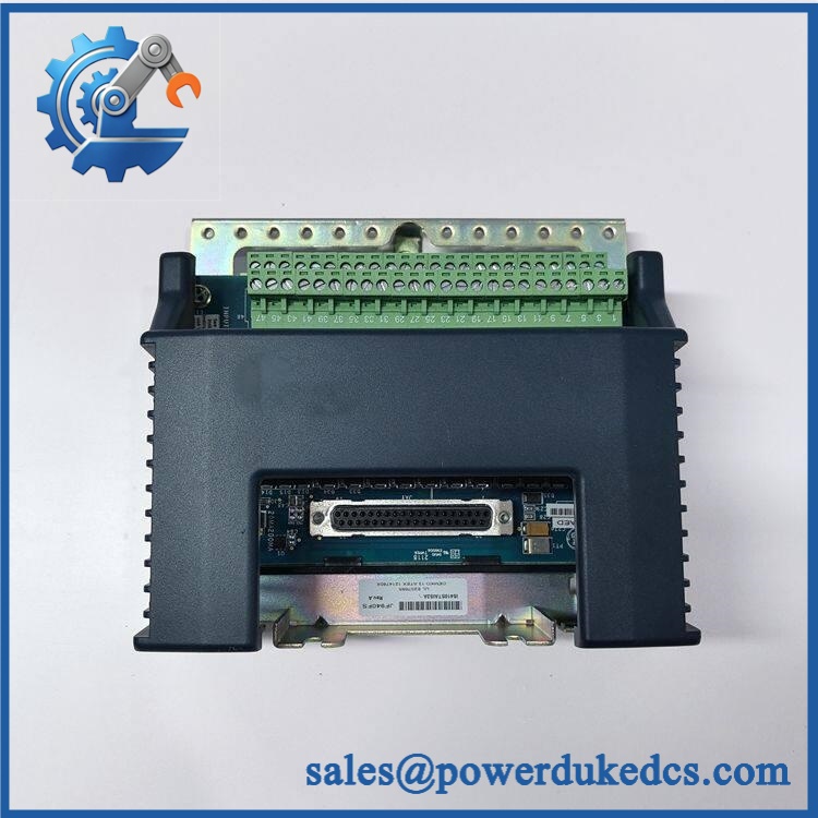
- GE IS410STAIS2A
Application Scenarios & Pain Points
With this board installed correctly, the Mark VIeS controller receives a structured analog field interface; without it, a perfectly healthy YAIC pack has no valid field termination path.
Process Measurement in Power Generation
A combined-cycle plant may use the STAI architecture for pressure, flow, temperature-transmitter, or other continuous analog measurements. The board supports 10 analog input channels, allowing several process variables to share one simplex interface assembly.
Turbine Auxiliary Systems
For lube-oil, seal-oil, hydraulic, or auxiliary-skid instrumentation, the 2-wire, 3-wire, 4-wire, and externally powered transmitter support can simplify field-interface selection. Wiring should still be checked against the project drawings before reconnection.
Functional Safety Applications
Mark VIeS installations can place the STAI/YAIC assembly inside a safety-related control architecture. GE specifies IEC 61508 compliance for the configuration, making configuration control and replacement traceability particularly important.
High-Temperature Control Cabinets
In a cabinet environment reaching 50°C+, verify ventilation, power-supply loading, terminal tightness, and enclosure condition before blaming the terminal board for unstable analog readings.
Legacy-to-Safety Migration Projects
Sites transitioning from conventional Mark VIe I/O toward Mark VIeS safety hardware should not assume that an STAI board can replace an older STAI/PAIC assembly without engineering review. The YAIC pack, safety configuration, terminal arrangement, and controller software all form part of the replacement architecture.
🚨 Common Error Codes & Diagnostic Symptoms
Symptom/Code: Incorrect Terminal Board / I/O Identification Diagnostic
→ Diagnosis: The YAIC pack is not recognizing the expected STAI terminal-board identity, or the installed board configuration does not match the controller database. GE specifically documents incorrect terminal-board checking as part of the diagnostic system.
→ Action: Verify identity, connector seating, pack compatibility, and configuration; replace the terminal board if the identity fault follows the hardware.
Symptom/Code: Multiple Analog Inputs Simultaneously Read Invalid or Out of Range
→ Diagnosis: A shared terminal-board interface, power source, common reference, or YAIC connection is more likely than simultaneous transmitter failure.
→ Action: Check field supply, wiring, connector integrity, and YAIC diagnostics before replacing individual transmitters.
Symptom/Code: Analog Output Command Present but Field Current Is Incorrect
→ Diagnosis: Inspect the 0–20 mA output circuit, field load, wiring polarity, and YAIC/terminal-board interface. A failed output path can also originate in the I/O pack rather than the STAI board.
→ Action: Test the output using a calibrated current measurement and isolate the board from the pack before declaring either component defective.
🚨 Cross-Reference & Lifecycle Migration
Cross-Reference
- is the Simplex Analog I/O terminal board for the Mark VIeS safety platform.
- The defined associated I/O pack is IS420YAICS1B.
- The corresponding TMR terminal-board family is IS410TBAIS1C, which also uses packs but supports one or three packs depending on architecture.
- The uses the S2 terminal style, with a right-angle header accepting pluggable terminal blocks; earlier STAI revisions used different termination arrangements.
- Do not treat an older STAI revision as a universal direct substitute without checking the project wiring and safety documentation.
Firmware and Configuration
The itself is a terminal board, so firmware is principally associated with the connected YAIC I/O pack rather than being flashed into the terminal board as though it were a standalone processor.
When replacing the board, however, the YAIC pack must correctly identify the terminal board, and the controller configuration must match the intended I/O assignment. GE specifically lists incorrect terminal-board checking as a diagnostic function.
Lifecycle Status
Status: Active
GE’s current Mark VIeS Functional Safety System documentation lists and identifies as its associated I/O pack.
For stock planning, active status reduces immediate obsolescence pressure, but a safety-system spare should still be controlled by exact part number and revision. A lower quantity may be acceptable when OEM lead time is short; critical installed systems should still retain a validated spare according to the site’s safety and maintenance policy.
Field Engineer’s Tech Notes
Warning 1 — Do not confuse the terminal board with the YAIC I/O pack.
The is not the . They are two separately orderable components. Receiving should verify that the quotation, packing list, and physical hardware identify the component actually required by the cabinet BOM.
Warning 2 — The S2 termination arrangement matters.
The S2 revision uses a right-angle header with pluggable terminal blocks. Earlier STAI revisions use different termination arrangements. Moving terminal plugs between revisions without checking the wiring schedule can create a channel-mapping error even when the board appears mechanically compatible.
One more practical point: the board supports several analog input spans. Never infer the active signal range from the terminal number alone. Confirm the controller configuration and loop design before applying field power.
Strict QA & Testing SOP
Step 1 — Inbound Identity Verification
Record:
- Manufacturer: GE
- Part number:
- Hardware revision
- Serial or manufacturing identifier where present
- Terminal-block configuration
- Associated YAIC pack requirement
Photograph the complete nameplate and terminal interface.
Step 2 — Physical Inspection
Check the board and assembly for:
- Cracked housing
- Bent header contacts
- Damaged terminal plugs
- Oxidation
- Moisture exposure
- Loose mounting hardware
- Contaminated contacts
Because this is a field termination assembly, connector condition deserves the same attention as PCB condition.
Step 3 — Terminal Identification Test
Install the board with a compatible YAIC pack in a controlled test arrangement. Confirm that the I/O pack correctly identifies the STAI board and does not report an incorrect-terminal-board diagnostic.
Step 4 — Analog Input Verification
Use calibrated voltage and current sources to test representative input ranges:
- 1–5 VDC
- 0–20 mA
- ±5 VDC
- ±10 VDC
- ±1 mA where applicable
Verify channel scaling, stability, and diagnostic response.
Step 5 — Analog Output Verification
Command both output channels through the applicable 0–20 mA range. Record measured current at several points across the range and compare against the configured output value.
Step 6 — Communication and I/O Test
Verify:
- YAIC recognition
- Controller communication
- Terminal-board identity
- Channel status
- Analog input values
- Analog output feedback
- Diagnostic status
Step 7 — Extended Run
Operate the assembly under representative load where the test rig permits. Monitor power stability, analog drift, communication continuity, and abnormal temperature rise.
Step 8 — QC Documentation
Create a controlled report containing:
- Exact part number
- Hardware revision
- Serial number
- Associated YAIC pack
- Input-channel test results
- Output-channel test results
- Diagnostic results
- Test date
- Technician identification
Step 9 — Final Preservation
After acceptance, protect the terminal board against ESD, moisture, dust, and connector damage. Use suitable antistatic packaging and mechanical protection before warehouse placement.
Test videos are available when visual evidence is included in the individual inspection package.
Buyer’s FAQ
A: Do not treat the terminal board as a generic hot-swappable device. This assembly interfaces directly with field wiring and a safety-rated YAIC architecture. Follow the site’s approved electrical isolation and Mark VIeS maintenance procedure before removing terminal hardware.
Q: Is the included with ?
A: No. GE identifies as a separately ordered I/O pack for the . The terminal board and I/O pack should therefore be specified independently on the procurement record.
Q: How do I verify a New Original unit?
A: Check the GE nameplate, exact identification, hardware revision, terminal arrangement, physical construction, and traceability documentation. For a safety application, request serial-level documentation and verify that the delivered hardware matches the approved BOM.
Q: What warranty should I require?
A: State the warranty period and product condition explicitly on the quotation. For a critical Mark VIeS spare, the acceptance package should include physical inspection, terminal-board identification, YAIC communication testing, and analog I/O verification rather than a simple power-on statement.











 Start Chat


