

Description
- Model: IS410STCIS2A
- Brand: GE General Electric
- Series: Mark VIeS Functional Safety System
- Part Type: STCI 24 VDC Contact Input Terminal Board
- Core Function: Provides the field termination and contact-voltage interface for the Mark VIeS IS420YDIAS1B contact-input I/O pack, handling 24 discrete inputs in a simplex safety configuration.
- Key Specs: 24 inputs, 24 VDC nominal wetting voltage, 20–32 VDC permitted wetting range, 1 ms SOE sampling, DIN-rail mounting, and IEC 61508 safety-rated configuration.
- Important Procurement Detail: The terminal board and IS420YDIAS1B I/O pack are separately orderable. The STCI board should not be represented as a complete intelligent I/O module by itself.
Product Introduction
A failed contact-input circuit can look deceptively simple in the field: one limit switch, pressure switch, or trip contact stops reporting, yet the actual fault may sit in the terminal board, wetting-voltage circuit, wiring, or I/O pack. The GE IS410STCIS2A is the 24 VDC STCI contact-input terminal board for the Mark VIeS safety architecture, providing the physical connection between up to 24 discrete process contacts and the associated IS420YDIAS1B I/O pack.
Architecturally, this is a simplex terminal-board assembly, not a standalone processor. The board uses a 24 VDC nominal floating contact-wetting source, permits 20–32 VDC, supports a 1 ms Sequence of Events sample rate, and mounts on a DIN rail through the specified carrier arrangement. The complete termination assembly, including the cover and I/O pack, is specified at approximately 17.0 × 15.7 × 15.3 cm (height × width × depth).
Core Technical Specifications
| Parameter | Value |
|---|---|
| Manufacturer | GE General Electric |
| Model | IS410STCIS2A |
| Product Family | Mark VIeS |
| Product Type | STCI Contact Input Terminal Board |
| Product Description | Mark VIeS 24 VDC Contact Input |
| I/O Pack | IS420YDIAS1B, 1 required and ordered separately |
| Configuration | Simplex |
| Number of Channels | 24 discrete inputs |
| Contact-Wetting Voltage | 24 VDC nominal |
| Minimum Wetting Voltage | 20 VDC |
| Maximum Wetting Voltage | 32 VDC |
| Wetting Current | 110 mA |
| Wetting Source | Floating, supporting ground-fault detection |
| SOE | Yes |
| SOE Sampling Rate | 1 ms |
| Contact Input Line Monitoring | No |
| Diagnostic Functions | Power-up self-test, loss of contact-input voltage, non-responding contact-input background test, incorrect terminal-board detection |
| Field Wiring | 24 AWG minimum to 12 AWG maximum |
| Field Termination | Euro-style box-type terminal blocks |
| Wetting-Power Connector | Mate-N-Lok receptacle, AMP 350766-1 |
| I/O Pack Power Connector | Micro Mate-N-Lok, AMP 1445022-3 |
| I/O Pack Control Power | 24/28 VDC, 6.8 W maximum per YDIA |
| Mounting | DIN rail |
| Safety Rating | IEC 61508 compliant |
| Hazardous Location Capability | Class I, Division 2 / Class II, Zone 2 / ATEX, subject to specified configuration |
| G3 Compliance | Yes |
| Operating Temperature | -40°C to +70°C |
| Storage Temperature | -40°C to +85°C |
| Complete Termination Dimensions | 17.0 × 15.7 × 15.3 cm H × W × D, including cover and I/O pack |
| Module Cover P/N | 151X1202YE04PP01BL |
| Lifecycle Status | Active |
| Standalone Memory | None; intelligence resides in the associated YDIA I/O pack |
GE’s current Mark VIeS functional-safety documentation specifically identifies IS410STCIS2A as the 24 VDC version and IS410STCIS4A as the 48 VDC version. Do not substitute the S4A simply because the mechanical format appears similar; their contact-wetting voltage ranges are materially different.
Power calculations should also distinguish the terminal-board contact-wetting supply from the I/O pack’s control power. The YDIA pack is specified at up to 6.8 W, while the STCI provides the 24 VDC contact-wetting source at up to 110 mA (an important distinction when sizing the cabinet’s 24 VDC supply).
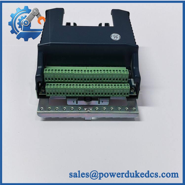
GE IS410STCIS2A
Application Scenarios & Pain Points
In a gas-turbine protection cabinet, the STCI can interface 24 discrete contacts such as permissive switches, status contacts, and protective process devices. At 70°C cabinet ambient, the specified operating-temperature limit becomes a real design constraint rather than a catalog footnote.
For steam-turbine auxiliary systems, the 1 ms SOE capability is particularly useful when engineers need to establish the sequence of discrete events around a trip or permissive transition. Check the controller time base as well; terminal-board sampling does not by itself define the complete system event-resolution chain.
In oil and gas facilities, hazardous-area approval can determine whether a replacement is acceptable. The documented Mark VIeS configuration supports Class I, Division 2 / Zone 2 / ATEX applications, but the complete assembly and installation conditions must remain within the certified configuration.
With a correctly matched IS420YDIAS1B, the STCI supplies the intended 24 VDC contact interface and diagnostic functions. Without the correct I/O pack pairing, the terminal board should not be treated as a functional replacement for a complete Mark VIeS contact-input module.
During legacy migration, retain the original terminal-board part number in the engineering change record. A 24-channel count alone is not enough to establish interchangeability when wetting voltage, safety architecture, terminal style, and diagnostics differ.
🚨 Common Error Codes & Diagnostic Symptoms
Symptom/Code: Incorrect Terminal Board / Configuration Diagnostic → Diagnosis: The controller detects that the installed terminal-board identity does not correspond to the expected Mark VIeS configuration. → Action: Verify the IS410STCIS2A identity and associated IS420YDIAS1B configuration; replace the incorrect or defective assembly.
Symptom/Code: Loss of Contact Input Voltage → Diagnosis: The 24 VDC floating wetting supply may be absent or outside its specified 20–32 VDC range, preventing valid contact detection. → Action: Measure the wetting supply at the terminal board, inspect the power connector and source, then replace the terminal board if the internal supply fails testing.
Symptom/Code: Non-Responding Contact Input During Background Test → Diagnosis: The input circuit, field wiring, contact device, terminal connection, or YDIA input electronics may be defective. → Action: Isolate the field device and simulate the contact locally; replace the failed hardware after the fault is proven to follow the module.
🚨 Cross-Reference & Lifecycle Migration
The IS410STCIS2A is the documented 24 VDC STCI terminal-board version. Its direct I/O-pack pairing is , which must be ordered separately. The corresponding IS410STCIS4A is the 48 VDC STCI variant and is not a universal substitute.
GE identifies the as Active in its current Mark VIeS functional-safety documentation. That makes it materially different from a legacy/obsolete spare requiring immediate strategic hoarding.
Lifecycle status: Active. For critical safety-system inventory, stocking should still reflect plant criticality and supplier lead time. One verified spare per critical control location can be sensible where replacement access is restricted or a turbine outage carries substantial cost.
Firmware flashing does not apply to the passive STCI terminal board itself. The associated is the intelligent I/O pack and is therefore the component for which firmware and application compatibility must be verified.
Do not use IS410STCIS4A as a firmware or voltage “upgrade.” Its 48 VDC contact-wetting architecture is electrically different from the 24 VDC design.
Field Engineer’s Tech Notes
First warning: don’t confuse contact voltage with I/O-pack control power. The STCI’s field contact-wetting supply is 24 VDC nominal, 20–32 VDC, while the attached YDIA I/O pack has its own 24/28 VDC control-power requirement. Diagnose them as separate electrical paths.
Second warning: preserve the complete terminal-board/I/O-pack pairing. The is designed around . Before removing a field assembly, photograph the terminal labels and wire positions, then compare them with the approved Mark VIeS drawing (especially the wetting-power connection).
Use ESD precautions around the YDIA electronics. The STCI terminal board provides field wiring, but the attached I/O pack contains the active electronic circuitry that performs diagnostics and communicates with the safety controller.
Strict QA & Testing SOP
Step 1 — Inbound inspection. Verify , serial/date markings where present, revision, terminal labels, cover, mounting hardware, and physical condition. Photograph the complete assembly and all identification markings.
Step 2 — Mechanical inspection. Examine the DIN-rail carrier, retaining hardware, Euro-style terminal blocks, connectors, wiring terminals, and protective cover. Check for cracked insulation, loose hardware, corrosion, and heat discoloration.
Step 3 — Wetting-voltage test. Using a controlled laboratory source, verify the contact-wetting circuit around the 24 VDC nominal / 20–32 VDC specified range. Confirm the floating-source behavior required for ground-fault detection.
Step 4 — YDIA integration test. Install an approved I/O pack and verify correct terminal-board recognition, startup diagnostics, LED health indications, and controller communication.
Step 5 — Contact-input simulation. Test all 24 input channels individually using controlled dry-contact or equivalent simulation. Verify positive/negative state transitions, diagnostic response, and the expected SOE behavior.
Step 6 — Background diagnostics. Confirm the system can detect loss of contact-input voltage and a non-responding input under the approved test procedure. Record each diagnostic result.
Step 7 — Final QC and packaging. Record serial number, test values, inspector, test date, and pass/fail result. Refit the protective cover, place the electronics in ESD-safe packaging, and protect the terminal blocks against impact.
Test videos are available for documented visual evidence of the incoming inspection and functional test sequence.
Buyer’s FAQ
Can the be hot-swapped?
Do not assume so. It is part of a safety-related contact-input circuit, and removing the terminal assembly can interrupt contact-wetting voltage and field indications. Follow the approved Mark VIeS maintenance and isolation procedure before removal.
How can I verify a New Original unit?
Match the identification, physical terminal arrangement, cover, mounting hardware, and associated configuration. Request clear label photographs and an incoming test record; packaging condition alone does not establish authenticity.
What warranty should appear on the purchase order?
State the warranty period and exact condition classification in writing. For New Original, New Surplus, or Refurbished inventory, the warranty should explicitly cover functional failure and define the return process.
What HS Tariff Code and Country of Origin should be declared?
The final HS classification must be determined under the importing country’s tariff schedule. Commercial listings may suggest classifications such as 8538-series component headings, but that is not a substitute for a broker-approved determination. COO likewise must come from the actual inventory lot and supporting documentation; retain it with the commercial invoice and packing list.











 Start Chat


