

Description
- Model: IS420ESWBH3AX
- Brand: GE General Electric
- Series: Mark VIe / Mark VIeS
- Part Type: ESWB Industrial Ethernet / IONet Switch
- Core Function: Provides the dedicated Ethernet switching layer between Mark VIe controllers and distributed I/O packs, carrying the real-time IONet traffic required by the control architecture. GE identifies the ESWB family specifically for Mark VIe and Mark VIeS IONet applications.
- Key Specs: 16 × 10/100Base-TX copper RJ-45 ports, no integrated fiber ports, 24/28 VDC dual redundant power inputs, 1 A maximum input, 256 KB packet buffer, and 4K MAC-address capacity.
- Cooling / Mounting: Fanless convection cooling with DIN-rail mounting through a separately selected GE mounting clip.
- Part-Number Note: GE documentation lists the base hardware as IS420ESWBH3A; the supplied IS420ESWBH3AX should therefore be preserved exactly as marked for procurement traceability rather than silently normalizing the suffix.
Product Introduction
A turbine-control network fault can remove an entire group of I/O packs even when every field instrument remains healthy. The GE IS420ESWBH3AX sits at that communication bottleneck: it is the 16-port, all-copper ESWB IONet switch used to carry Ethernet traffic between Mark VIe controllers and distributed I/O. Unlike an office Ethernet switch, this hardware belongs to the dedicated control-network architecture, where link integrity and deterministic traffic handling directly affect controller-to-I/O communication.
Physically, the H3A configuration is the all-copper ESWB variant—16 RJ-45 10/100Base-TX ports with no integrated fiber ports—while the H1A/H2A versions add multimode fiber interfaces and H4A/H5A versions add single-mode fiber interfaces. The switch accepts 24/28 VDC, has two independent power inputs that are diode-OR’d for redundancy, and uses natural convection rather than an internal fan (important in dusty turbine-control cabinets).
Core Technical Specifications
| Parameter | Value |
|---|---|
| Manufacturer | GE General Electric |
| Model | IS420ESWBH3AX |
| Base Hardware Reference | IS420ESWBH3A |
| Product Family | Mark VIe / Mark VIeS |
| Part Type | Industrial Ethernet / IONet Switch |
| Switch Architecture | Unmanaged industrial Ethernet switch |
| Copper Ports | 16 |
| Copper Interface | 10/100Base-TX, RJ-45 |
| Fiber Ports | None |
| Ethernet Standards | IEEE 802.3, 802.3u, 802.3x |
| Duplex | Automatic full/half-duplex negotiation |
| Auto MDI/MDIX | Supported |
| Packet Buffer | Minimum 256 KB |
| MAC Address Table | 4K addresses |
| Power Inputs | 2 independent inputs |
| Power Redundancy | Diode-OR’d redundant inputs |
| Nominal Supply | 24 / 28 VDC |
| Maximum Input Current | 1 A |
| Power Connector | Phoenix contact, MC 1.5/S-STF-3.81, 2 supplied |
| Cooling | Natural convection, fanless |
| Dimensions | Approximately 188 × 86 × 56 mm (H × W × D) |
| Mounting | DIN rail with separately purchased qualified clip |
| Operating Temperature | -40°C to +70°C |
| Storage Temperature | -40°C to +85°C |
| Humidity | 5–95% RH, non-condensing |
| G3 Compliance | Yes |
| Hazardous Location Capability | Class I Div. 2 / Class II Zone 2 / ATEX configurations |
| Safety Classification | Non-interfering for the documented Mark VIeS configuration |
| Application | Controller-to-I/O network communication |
| Standalone Firmware | Unmanaged switch; no user application firmware configuration |
| Memory / Buffer | 256 KB minimum packet buffer; 4K MAC entries |
GE’s ESWB documentation specifies the H3A version as 16 copper ports with no fiber ports, while all ESWB variants share the 24/28 VDC redundant supply architecture, 256 KB minimum buffer, 4K MAC table, and 10/100 Ethernet capability. The published mechanical envelope is 18.8 × 8.6 × 5.6 cm.
For heat-load calculations, the important value is the 1 A maximum input rating, not a processor power figure. There is no conventional application-memory limit because this is an unmanaged network switch; the 256 KB packet buffer and 4K MAC-address table are the relevant internal data resources.
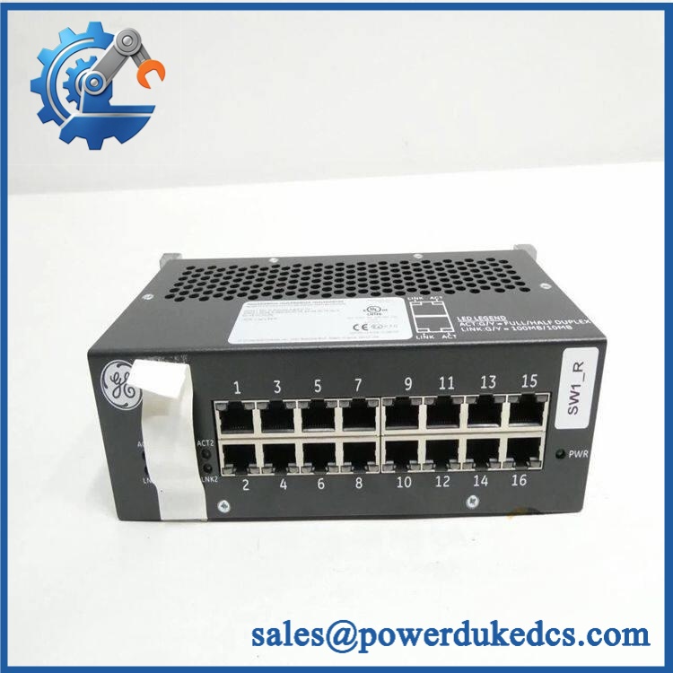
GE IS420ESWBH3AX
Application Scenarios & Pain Points
In a gas-turbine control cabinet, one ESWB can aggregate multiple copper IONet connections from controllers and I/O packs. At 70°C ambient, the switch remains within the published maximum operating-temperature range, but cabinet airflow and power-source stability still deserve inspection.
For combined-cycle power plants, the all-copper H3A configuration is useful where the IONet network remains within the copper Ethernet architecture. A failed switch can appear as multiple unrelated I/O communication failures because several nodes share the same physical network path.
In steam-turbine installations, dual power inputs provide a second supply path to the switch. Verify both feeds independently; one failed input may remain hidden until the surviving source also becomes unavailable.
For oil and gas facilities, the hazardous-location rating can be a procurement requirement rather than a convenience. The documented ESWB family supports applicable Class I Division 2, Zone 2, and ATEX configurations under specified installation conditions.
During legacy migration, the absence of fiber on H3A is decisive. If an existing cabinet uses an optical uplink, changing to H3A is not a like-for-like substitution; select the corresponding H1A, H2A, H4A, or H5A optical variant according to the actual network design.
🚨 Common Error Codes & Diagnostic Symptoms
Symptom/Code: Multiple I/O Packs Drop Offline Together → Diagnosis: A shared ESWB communication path may be resetting, losing power, or experiencing an internal hardware fault. GE has documented network-switch failures that can cause loss of communication from a group of I/O packs. → Action: Verify both power inputs, inspect switch LEDs and upstream/downstream links, then replace the ESWB if the fault follows the switch.
Symptom/Code: Repeated Communication Reset Every Few Minutes to Several Hours → Diagnosis: Intermittent power-supply degradation, particularly involving aging electrolytic capacitors, can produce repeated switch resets. GE’s service material identifies capacitor leakage as a common failure mechanism on older Mark VIe network switches. → Action: Measure both supply paths under load, inspect for capacitor leakage or audible hissing/crackling, and replace the switch when power-supply degradation is confirmed.
Symptom/Code: Individual Port Shows No Link → Diagnosis: Check the RJ-45 connector, Cat 5e cable, remote device, and port LED state before condemning the switch. A broken conductor or incorrect patching can mimic a failed Ethernet port. → Action: Perform a known-good cable and endpoint test; replace the ESWB only when the fault remains with the switch port.
🚨 Cross-Reference & Lifecycle Migration
GE documentation identifies the ESWB family as:
- IS420ESWBH1A: 16 copper + 1 multimode 100FX fiber port
- IS420ESWBH2A: 16 copper + 2 multimode 100FX fiber ports
- IS420ESWBH3A: 16 copper, no fiber
- IS420ESWBH4A: 16 copper + 1 single-mode 100LX10 fiber port
- IS420ESWBH5A: 16 copper + 2 single-mode 100LX10 fiber ports.
The supplied IS420ESWBH3AX corresponds to the H3A all-copper configuration in the available technical documentation; retain the complete “X” suffix in the warehouse record until the physical nameplate is reconciled with the controlled GE documentation. Secondary listings consistently describe the X-marked unit as the 16-port, no-fiber H3A switch.
Lifecycle status: Active for the documented H3A ESWB hardware family. GE’s current documentation lists the ESWB H1A–H5A variants as active.
For a legacy Mark VIe cabinet, stock the exact port configuration. Do not substitute a fiber-equipped H1A/H2A/H4A/H5A for H3A simply because the electrical envelope is similar; the network topology changes materially.
Firmware flashing is normally not a field-maintenance requirement for this unmanaged switch. Network behavior is determined primarily by the switch hardware and physical topology rather than a user-loaded application image.
Field Engineer’s Tech Notes
First warning: verify the fiber requirement before ordering. H3A has zero integrated fiber ports. I have seen network-replacement jobs delayed because the replacement was mechanically correct but lacked the optical interface used by the original cabinet. The GE ordering matrix makes this distinction explicit.
Second warning: check both DC power inputs. The switch has redundant power inputs that are diode-OR’d. Do not diagnose an intermittent network fault from one voltage measurement alone; measure both sources and verify each branch under realistic load conditions.
Keep copper Ethernet cabling away from high-current switching conductors where cabinet layout permits. Also protect the RJ-45 retention tabs and connector bodies during maintenance; damaged mechanical retention can create intermittent link faults that are difficult to reproduce.
Strict QA & Testing SOP
Step 1 — Inbound inspection. Confirm the complete IS420ESWBH3AX marking, base H3A designation, serial/date information, port count, physical housing, connector condition, and DIN-rail mounting hardware. Photograph the nameplate and all ports.
Step 2 — Mechanical inspection. Check the housing, Phoenix power connectors, RJ-45 sockets, LED window, mounting points, and retaining hardware. Inspect for cracked plastic, corrosion, contamination, and evidence of overheating.
Step 3 — Power verification. Apply controlled 24/28 VDC power within the approved supply range. Test each redundant input independently and then together, confirming normal operation and acceptable current draw.
Step 4 — Port validation. Connect known-good Cat 5e test cables and validated Ethernet endpoints. Exercise all 16 copper ports individually and verify link, activity, speed, and duplex indications.
Step 5 — Network-load testing. Use an approved Mark VIe test environment to generate representative traffic through multiple ports. Confirm stable forwarding, absence of repeated resets, and correct LED behavior.
Step 6 — Thermal observation. Operate the switch under representative port loading and inspect for abnormal localized heating. Because the unit is convection cooled, verify that the enclosure remains free of blocked airflow paths.
Step 7 — Final QC and packaging. Record serial number, input-voltage measurements, port-test results, thermal observations, inspector, test date, and pass/fail status. Return the unit to ESD-safe packaging and protect all Ethernet and power connectors.
Test videos are available for the power-input and 16-port communication verification stages when documented QC evidence is required.
Buyer’s FAQ
GE Mark VIe architecture supports online replacement of certain control-system components, but do not treat the ESWB as an ordinary plug-and-play office switch. Isolate or follow the approved maintenance procedure for the specific network architecture, because removing a shared switch can interrupt communication to multiple I/O packs. GE describes hot-swap capability at the Mark VIe system level, but the actual maintenance procedure governs the field action.
How do I verify a New Original unit?
Match the nameplate, H3A port configuration, 16 RJ-45 ports, power connector arrangement, housing, serial information, and physical construction against the approved procurement record. A clean or repackaged switch is not enough to establish original condition.
What warranty should be specified?
Put the warranty period and condition classification directly on the purchase order. For New Original, New Surplus, or Refurbished inventory, the warranty should identify the exact part number and cover functional failure after installation.
Does it require the latest firmware pre-loaded?
This is an unmanaged IONet Ethernet switch, so it does not use a user-configured application firmware workflow comparable to a Mark VIe controller or I/O pack. The important acceptance checks are hardware identity, port configuration, power redundancy, link behavior, and compatibility with the installed IONet architecture.











 Start Chat


