

Description
- Model: GE IS420YDOAS1B
- Brand: General Electric
- Series: Mark VIe / Mark VIeS
- Part Type: YDOA Discrete Output I/O Pack
- Core Function: Interfaces Mark VIeS control logic with a compatible discrete-output terminal board and can control up to 12 relay outputs.
- Key Specs: 12-channel output architecture, BPPC-based processor, dual RJ-45 Ethernet interfaces, DC-37 terminal-board connection, 24/28 VDC control supply, 19.8 W maximum pack power, and operation from -40°C to +70°C.
- Safety Position: Used with approved Mark VIeS relay terminal boards in simplex or TMR configurations; the safety certification boundary depends on the complete approved hardware combination.
Product Introduction
The GE IS420YDOAS1B sits between the Mark VIeS controller network and the physical relay-output terminal board. It is the active YDOA discrete-output I/O pack, receiving commands over one or two I/O Ethernet networks and driving up to 12 relay channels through the associated terminal-board assembly. That arrangement keeps processing electronics separate from field termination, which is useful when troubleshooting a failed output path (the I/O pack and terminal board should be tested independently).
From a lifecycle standpoint, this is an important Mark VIeS component because the same YDOA pack serves several approved terminal-board architectures. IS410TRLYS1B, IS410TRLYS1D, IS410TRLYS1F, and IS410TRLYS2F have different relay and monitoring functions, so the terminal-board suffix cannot be ignored when ordering a replacement. In field deployments, maintaining New Original or fully tested spare YDOA units is particularly useful where a safety-system outage could extend a turbine shutdown.
Core Technical Specifications
| Parameter | Value |
|---|---|
| Manufacturer | GE General Electric |
| Model | IS420YDOAS1B |
| Series | Mark VIe / Mark VIeS |
| Functional Acronym | YDOA |
| Product Type | Discrete Output I/O Pack |
| Application | Mark VIeS relay/discrete output |
| Maximum Output Channels | 12 |
| Output Type | Relay/discrete output through compatible terminal board |
| Processor Board | BPPC |
| Ethernet Interfaces | 2 × RJ-45 |
| I/O Network | Mark VIe I/O Ethernet architecture |
| Terminal-Board Interface | DC-37 |
| Power Connector | Micro Mate-N-Lok |
| Control Supply | 24/28 VDC |
| Maximum DC Control Power | 19.8 W including relay-coil drive power |
| Maximum Output Relays | Up to 12 |
| Relay Feedback | Terminal-board dependent |
| Diagnostic Functions | Status LEDs, I/O-pack health variables, terminal-board/configuration checks |
| Response Time | Approximately 6 ms for the I/O pack |
| Construction | Aluminum enclosure |
| Mounting | Installed with approved DIN-rail terminal-board assembly |
| Operating Temperature | -40°C to +70°C |
| Storage Temperature | -40°C to +85°C |
| Approx. Module Dimensions | 82.6 × 41.9 × 121.4 mm |
| Approx. Module Weight | 0.34 kg |
| Conformal Coating | Configuration dependent |
| Firmware | Application/system dependent |
| Hot Replacement | Do not assume live replacement |
Terminal-board compatibility
GE documents the following Mark VIeS relay-output terminal boards for the IS420YDOAS1B:
| Terminal Board | Functional Arrangement | Redundancy |
|---|---|---|
| IS410TRLYS1B | 12 Form-C relays with coil sensing | Simplex or TMR |
| IS410TRLYS1D | 6 relay outputs with solenoid-integrity sensing | Simplex or TMR |
| IS410TRLYS1F | 12 Form-A relay contacts with TMR contact voting | TMR |
| IS410TRLYS2F | 12 Form-B relay contacts with TMR contact voting | TMR |
This is not a cosmetic distinction. The terminal board determines the actual field-output circuit, relay arrangement, feedback method, and safety architecture. The YDOA pack should therefore be specified together with the terminal-board part number during procurement.
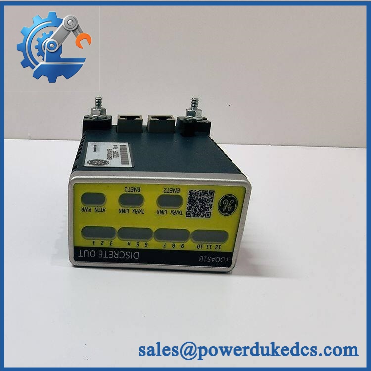
- GE IS420YDOAS1B
Application Scenarios & Pain Points
Gas-turbine shutdown functions: A YDOA installation can control relay-based commands associated with turbine auxiliaries, valves, shutdown circuits, and other discrete field equipment. Up to 12 output channels are available from one I/O pack.
Safety instrumented systems: In a Mark VIeS installation, the YDOA forms part of an IEC 61508-oriented safety architecture when paired with the approved terminal board and system configuration. Relay feedback can provide useful evidence that a commanded output actually changed state.
TMR turbine protection: Three YDOA packs can be used with supported TMR terminal-board arrangements. This gives the system three independent I/O paths, but the complete voting architecture must be preserved during maintenance.
Solenoid applications: The TRLY terminal-board family includes configurations with solenoid-related monitoring and field-power arrangements. A technician should identify the exact terminal-board suffix before selecting a replacement YDOA.
High-temperature control cabinets: At 50°C+ ambient, pay attention to enclosure temperature and local airflow. The YDOA itself is rated for a broad operating range, but relay-coil heat from the terminal assembly contributes to the total cabinet thermal load.
🚨 Common Error Codes & Diagnostic Symptoms
Symptom/Code: YDOA I/O pack not recognized by the controller
→ Diagnosis: Possible loss of 24/28 VDC control power, Ethernet communication failure, connector damage, incompatible terminal-board configuration, or internal processor fault.
→ Action: Verify pack supply, I/O Ethernet links, DC-37 connection, and terminal-board identity before replacing the YDOA.
Symptom/Code: Commanded relay output does not match feedback
→ Diagnosis: On supported TRLY configurations, the terminal board provides relay feedback to the YDOA. A mismatch can result from a failed relay, field wiring fault, feedback circuit problem, or terminal-board issue.
→ Action: Test the command and feedback paths separately; replace the defective component after controlled verification.
Symptom/Code: Multiple relay outputs fail together
→ Diagnosis: A common YDOA power or communication problem is more likely when several channels fail simultaneously. A field supply or terminal-board common circuit can produce the same symptom.
→ Action: Check the shared control supply and YDOA health status before replacing individual field relays.
Exact numerical diagnostic identifiers depend on the installed Mark VIeS software and ControlST revision. The YDOA module does not have one universal standalone fault-code list.
🚨 Cross-Reference & Lifecycle Migration
Lifecycle Status: Active
GE’s current Mark VIeS documentation lists IS420YDOAS1B as the I/O pack used with multiple active TRLY relay-output terminal-board configurations. The same documentation identifies the terminal boards and the approved simplex/TMR relationships.
Compatibility data
- : Current YDOA discrete-output I/O pack.
- IS220YDOAS1B: Older generation YDOA platform. It should not be treated as an automatic substitute for in a safety-controlled installation.
- IS410TRLYS1B: 12 Form-C relay terminal board with coil sensing; supports one or three YDOA packs depending on architecture.
- IS410TRLYS1D: 6-output solenoid arrangement with integrity sensing.
- IS410TRLYS1F / S2F: TMR contact-voting configurations.
- IS410SRLYS2A: Separate simplex relay terminal-board architecture. Do not assume equivalence simply because it also uses YDOA.
- Firmware: YDOA contains application-controlled processing firmware; firmware revision must match the approved Mark VIeS software baseline. Firmware flashing is not a substitute for incorrect terminal-board hardware.
- Safety configuration: For an IEC 61508 application, changing the I/O pack or terminal board should be managed under the site’s functional-safety change-control process.
- Buffer-stock strategy: Because the YDOA serves several critical relay-output configurations, one tested spare can cover multiple approved configurations only when the installed terminal-board family and software baseline are documented. For TMR systems, preserve the required three-pack inventory level where the site’s maintenance strategy requires complete redundancy.
Field Engineer’s Tech Notes
Warning 1 — Do not order YDOA without identifying the terminal board.
The is not the complete relay-output circuit. TRLYS1B, TRLYS1D, TRLYS1F, and TRLYS2F implement materially different output architectures. Match the complete assembly before installation.
Warning 2 — Do not assume all three Ethernet connections are interchangeable.
The YDOA uses its Ethernet interfaces as part of the Mark VIe I/O network architecture. Cable routing and network assignment should remain consistent with the approved simplex, dual, or TMR topology. Check the actual network drawings before reconnecting a replacement.
Strict QA & Testing SOP
Step 1 — Inbound identity inspection
Verify , hardware revision, serial/traceability markings, aluminum housing, connector condition, and label integrity.
Step 2 — Terminal-board compatibility check
Record the associated terminal-board model: IS410TRLYS1B, S1D, S1F, or S2F. Confirm whether the site uses simplex, dual, or TMR architecture.
Step 3 — Mechanical inspection
Check the enclosure, mounting interface, DC-37 connector, two RJ-45 ports, power connector, and protective surfaces.
Step 4 — Electrical pre-check
Verify power-input polarity and perform controlled resistance checks. The test fixture should provide the documented 24/28 VDC control supply.
Step 5 — Power-up test
Energize the YDOA on an approved test arrangement. Record supply voltage, current, startup sequence, LED status, and diagnostic health.
Step 6 — Ethernet test
Exercise the applicable I/O Ethernet interfaces and verify stable network communication with the test controller or approved simulation environment.
Step 7 — Output-channel simulation
Operate all 12 output channels through a compatible terminal-board test arrangement. Verify command response, relay actuation, and channel status indication.
Step 8 — Feedback testing
For terminal boards with relay or coil feedback, confirm that commanded and actual states are correctly reported to the host system.
Step 9 — Redundancy test
Where the unit is intended for TMR service, verify the applicable individual I/O-network and channel behavior without connecting the test device to live plant trip circuits.
Step 10 — QA documentation and packaging
Record measured power, output-channel results, feedback results, hardware identity, serial number, photographs, and final QC status. Test videos are available as supporting inspection evidence when requested. Package the I/O pack in ESD protection with all connectors mechanically protected.
Buyer’s FAQ — Dynamic Q&A
A: Do not assume live replacement. The YDOA can participate directly in relay-based control and safety functions, and the correct procedure depends on the Mark VIeS architecture and terminal-board arrangement. Use the approved GE and plant maintenance procedure.
Q: Is a standalone relay-output module?
A: No. It is the active I/O pack and works with a compatible terminal board. The terminal board provides the physical relay circuits and field connections, so both part numbers should be checked when determining compatibility.
Q: How can I verify New Original authenticity?
A: Check the complete identifier, hardware revision, serial/traceability markings, enclosure condition, connector quality, and documented functional-test results. For Mark VIeS safety applications, also verify that the delivered hardware matches the approved terminal-board configuration.
Q: What warranty should I require?
A: Require a written warranty tied to the exact serialized I/O pack and tested condition. The procurement file should include the model, revision, serial number, associated terminal-board type, power-up test, all-channel output test, feedback results where applicable, and warranty start date.











 Start Chat


