

Description
- Model: IS430SNUAH1A
- Brand: General Electric (GE)
- Series: Mark VIe
- Part Type: Universal I/O Assembly
- Core Function: Provides a configurable field interface for multiple analog and digital signal types, reducing the need for separate dedicated I/O hardware.
- Assembly Structure: The IS430SNUAH1A is described as a PUAAH1A I/O pack combined with an SUAAH1A terminal board.
- Channel Capacity: 16 simplex channels, with each channel configurable through ToolboxST for thermocouple, RTD, ±5/±10 V input, 4–20 mA input, 0–20 mA output, pulse accumulator, or digital-input functions.
- Processor Hardware: PUAAH1A uses a BPPC processor, a BCAR carrier board, and four MIO universal analog I/O boards.
- Power: A 28 VDC control-side supply is reported for the PUAA module.
- Physical Reference: One commercial technical record reports 260 × 220 × 40 mm and approximately 1.2 kg; verify against the actual cabinet drawing before freight or enclosure calculations.
Product Introduction
A plant does not always have the luxury of replacing every process signal with a dedicated I/O card. During legacy system maintenance, one cabinet may contain thermocouples, RTDs, current loops, voltage signals, pulse inputs, and discrete contacts. The IS430SNUAH1A addresses that mixed-signal requirement by providing sixteen individually configurable simplex channels in a single Mark VIe universal I/O assembly.
The assembly combines PUAAH1A and SUAAH1A hardware, with the signal type selected through ToolboxST rather than internal jumpers or switches (which is important when managing a New Surplus spare). Public technical records identify the assembly as Universal I/O, Mark VIe, and GE-part catalogs independently list IS430SNUAH1A under that description.
Core Technical Specifications
| Parameter | Value |
|---|---|
| Manufacturer | General Electric |
| Model | IS430SNUAH1A |
| Series | Mark VIe |
| Product Type | Universal I/O Assembly |
| Assembly | PUAAH1A I/O Pack + SUAAH1A Terminal Board |
| Channel Count | 16 simplex channels |
| Channel Configuration | Individually configurable |
| Thermocouple Input | Supported |
| RTD Input | Supported |
| Voltage Input | ±5 V or ±10 V |
| Current Input | 4–20 mA |
| Current Output | 0–20 mA |
| Pulse Accumulator | Supported |
| Digital Input | Supported |
| Processor | BPPC |
| Carrier Board | BCAR |
| Internal I/O Boards | 4 × MIO universal analog I/O boards |
| Configuration | ToolboxST |
| Internal Configuration Hardware | No internal jumpers, switches, or fuses required |
| Control-Side Supply | 28 VDC reported |
| Terminal Board | SUAAH1A |
| Cooling | Free convection |
| Published Temperature Reference | -30°C to +65°C reported for the processor/data-acquisition hardware |
| Published Dimensions | Approx. 260 × 220 × 40 mm |
| Published Weight | Approx. 1.2 kg |
The channel flexibility is the defining engineering feature. GE-related technical material describes the sixteen channels as individually configurable for the listed signal types, allowing one universal assembly to cover several conventional process-I/O requirements.
There is an important sourcing caveat around the physical and environmental figures. Commercial records are not fully consistent; for example, one source reports 260 × 220 × 40 mm / 1.2 kg, while another gives a much smaller weight. Use the actual unit and approved GE mechanical documentation for final packing calculations.
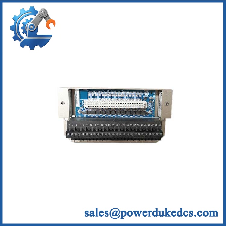
GE IS430SNUAH1A
Application Scenarios & Pain Points
In a mixed-signal turbine auxiliary cabinet, sixteen universal channels can be assigned according to the actual field instrumentation rather than forcing every signal into a dedicated I/O type. This is useful where spare-part variation has become a warehouse burden.
For temperature monitoring, individual channels can be configured for thermocouple or RTD service. The same assembly can also support voltage and current signals, which is useful during legacy migration projects where the instrumentation mix changes from one machine train to another.
At an installation exposed to 50°C+ cabinet temperatures, thermal margin should be checked before replacement. Public technical data reports a -30°C to +65°C range for the internal PUAA processor/data-acquisition hardware, with free-convection cooling.
During an engineering change, channel configuration is performed through ToolboxST rather than by moving hardware jumpers or DIP switches. That reduces physical setup changes but makes configuration-file control much more important.
For warehouse standardization, one universal-I/O spare may cover several signal types, but only when the site’s approved channel configuration and terminal-board arrangement are documented. A universal module is not automatically a universal replacement for every Mark VIe I/O assembly.
Common Error Codes & Diagnostic Symptoms
Symptom/Code: Channel reports the wrong signal state or implausible process value
→ Diagnosis: Incorrect ToolboxST channel configuration, wrong sensor type, wiring error, scaling mismatch, or acquisition-channel fault. Because channels are software-configurable, a configuration mismatch can resemble a hardware failure.
→ Action: Verify channel configuration and field wiring first; replace the module only after the input circuitry has been isolated.
Symptom/Code: I/O pack temperature diagnostic / over-temperature condition
→ Diagnosis: Excessive internal temperature can result from cabinet heat, restricted airflow, or module loading. The Mark VIe I/O architecture includes temperature monitoring, and one technical source reports approximately ±2°C sensor accuracy.
→ Action: Correct cabinet thermal conditions and inspect the module before replacement.
Symptom/Code: I/O communication or hardware-identification fault
→ Diagnosis: Possible power problem, network issue, incorrect I/O assembly, or configuration mismatch between the Mark VIe controller and the connected hardware. Mark VIe I/O packs transmit identification information to the host controller.
→ Action: Verify part identity, terminal-board relationship, I/O configuration, and network path before condemning the pack.
A universal numeric fault-code table for IS430SNUAH1A was not established in the public documentation reviewed. Use the actual Mark VIe ControlST diagnostic message and site alarm database for exact code interpretation.
Cross-Reference & Lifecycle Migration
Primary Assembly Identity
Current component catalogs identify:
— ASSEMBLY: UNIVERSAL I/O, MKVIe.
The assembly is described as:
PUAAH1A I/O Pack + SUAAH1A Terminal Board.
Related Universal I/O Hardware
The Mark VIe family also includes IS420PUAAH1A, identified as the universal I/O pack used within the assembly. That component should not be confused with the complete assembly.
Replacement Compatibility
The should not be declared a direct replacement for a conventional analog, RTD, thermocouple, or discrete I/O module without checking:
- channel configuration,
- SUAA terminal-board wiring,
- ToolboxST database,
- controller software baseline,
- field signal type,
- and cabinet mechanical arrangement.
Its universal nature provides flexibility, not unrestricted cross-compatibility.
Firmware Requirement
The available documentation indicates that the channel functions are configured through ToolboxST. No reliable evidence establishes a universal firmware-flashing requirement for every replacement . Firmware and application compatibility should therefore be checked against the installed Mark VIe configuration before commissioning.
Lifecycle Status
Lifecycle classification: Active catalog reference, with current OEM commercial availability requiring confirmation.
Recent component catalogs continue to list as an “ASSEMBLY: UNIVERSAL I/O, MKVIe,” which confirms ongoing documentation presence but does not independently prove unrestricted 2026 production availability.
For plants still operating Mark VIe, maintain at least one configuration-documented spare when lead time or application recovery risk is significant.
Field Engineer’s Tech Notes
Warning 1 — Do not change the sensor type without checking the configuration file.
A universal channel can be configured as RTD, thermocouple, current, voltage, pulse, or digital input. That flexibility is useful, but loading the wrong channel definition can create a perfectly healthy-looking module that produces invalid process values.
Warning 2 — Do not inventory the universal I/O pack and complete assembly as the same item.
PUAAH1A is the I/O pack; is the complete universal-I/O assembly with the SUAAH1A terminal board. Mixing those descriptions causes avoidable procurement and receiving errors.
Also check airflow. The published environmental reference assumes free-convection cooling, so a tightly enclosed cabinet with additional heat sources can reduce the practical temperature margin.
Strict QA & Testing SOP
Step 1 — Inbound identity inspection
Verify the full marking and record serial number, hardware revision, date information, and package identifiers. Photograph the nameplate before inventory acceptance.
Step 2 — Assembly completeness check
Confirm the presence of the expected combination. Record the I/O pack and terminal-board identifiers separately in the asset database.
Step 3 — Physical inspection
Inspect terminal blocks, connectors, mounting hardware, enclosure surfaces, PCB condition, and evidence of contamination or thermal damage.
Step 4 — Controlled power test
Apply the approved Mark VIe control-side supply and observe startup behavior. Record current draw, status indications, and temperature behavior. Do not use an assumed supply limit where the exact test documentation is unavailable.
Step 5 — Communication test
Connect the assembly to an approved Mark VIe test environment and verify that the controller recognizes the expected I/O hardware and terminal-board identity.
Step 6 — Channel functional testing
Test representative channels in each supported mode where the facility has the appropriate fixtures: thermocouple, RTD, voltage, 4–20 mA, 0–20 mA output, pulse, and digital input. Record scaling and signal accuracy against the approved test standard.
Step 7 — Configuration verification
Load or verify the intended ToolboxST configuration and confirm that channel assignments agree with the test record. This is especially important because the module has no internal jumpers or DIP switches for ordinary channel selection.
Step 8 — Thermal observation
Operate the assembly under representative load and monitor temperature. Investigate abnormal heating before release.
Step 9 — Final QA and packaging
Record all measured values, tested channel types, serial number, configuration revision, photographs, and technician sign-off. Place the assembly in ESD-safe packaging with mechanical protection. Test videos are available with the QC record for procurement review.
Buyer’s FAQ
A: Do not assume that live replacement is approved. This is a complete Mark VIe universal-I/O assembly with field wiring and controller communications, so removal can affect active process signals. Follow the site’s approved Mark VIe maintenance procedure and establish the required safe state first.
Q: Is just another name for ?
A: No. is the I/O pack, while is the complete universal-I/O assembly incorporating and . Treat them as separate inventory identities.
Q: How do I verify a New Original unit?
A: Request clear photographs of the GE part marking, serial number, hardware revision, and identifiers, and packaging labels. For controlled procurement, also obtain the pre-shipment test record and verify that the delivered assembly matches the site’s approved configuration.
Q: What warranty should I require?
A: Require written DOA and functional-failure coverage tied to the unit serial number. The warranty package should include the tested assembly identity and configuration record so that a return does not create uncertainty about which universal-I/O variant was actually supplied.











 Start Chat


