

Description
- Brand: GE Multilin
- Full Model Number: MMII-PD-1-2-120
- Lifecycle Status: Obsolete / Out of Production
- Core Function: Motor management, protection, monitoring, and control
- Top 3 Technical Specs: 120 VAC control supply; Panel-mounted display/keypad; Options 1 + 2 with process-control and enhanced motor-protection functions
- Stock & Condition: Physical stock verification required; New Surplus / Tested Refurbished; Emergency dispatch subject to QA cutoff
Module 3: Obsolescence & Supply Chain Deep Dive
When a legacy motor protection relay fails, the real cost starts before the replacement arrives: MCC downtime, engineering review, expedited freight, commissioning, and the risk of holding an unsuitable substitute. The GE Multilin MMII-PD-1-2-120 belongs to the Motor Manager II family and is a panel-mounted motor management unit with a display, designed around a 120 VAC control supply. Its ordering configuration combines both option sets, including process-control inputs and enhanced protection features. The model is documented as an out-of-production product, making verified replacement inventory important for facilities still operating MMII installations.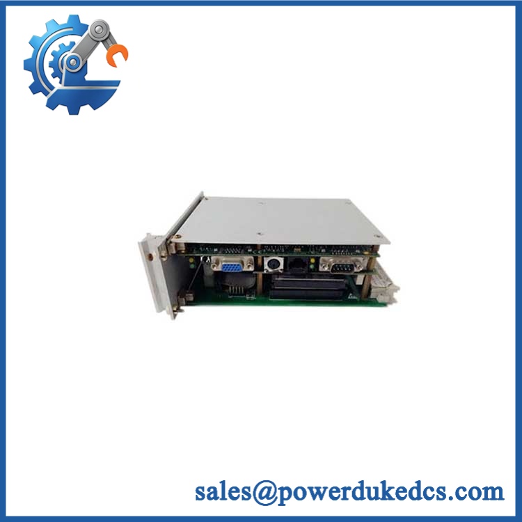
For a functioning legacy MCC, replacing the failed relay can produce a materially lower TCO than replacing the entire motor-control architecture. The cost avoidance comes from retaining existing field wiring, protection coordination, panel hardware, commissioning procedures, and engineering documentation. A correctly matched MMII-PD-1-2-120 also preserves the installed equipment strategy instead of forcing a larger migration project. The model uses a 120 VAC control input, supports 4–20 mA analog inputs, and is associated with EnerVista MMII software; one published specification also places its communications range at 1,200–19,200 bps.
Module 4: Compatibility & Replacement Matrix
| Replacement Scenario | Classification | Engineering / Procurement Guidance |
|---|---|---|
| Exact MMII-PD-1-2-120 for existing MMII installation | Drop-in Replacement | Preferred route when part number, option configuration, supply voltage, wiring, and mounting are matched |
| Same MMII family with configuration differences | Software Compatible — verification required | Confirm installed option set and configuration before commissioning |
| Replacement by a newer motor protection platform | Hardware Modification | Treat as a redesign involving wiring, panel fit, configuration, protection settings, and commissioning |
Estimated switch cost/time: For an exact, tested replacement already available on-site, allow roughly 2–6 hours for removal, installation, wiring verification, configuration review, and functional checkout. For a sourced replacement requiring inspection and expedited transport, planning should allow 1–5 business days, depending on location and carrier collection. These are engineering planning ranges, not guaranteed outage durations.
Field Traps — Watch Out
- Control-voltage mismatch: The final
-120designation identifies the 120 VAC control-voltage configuration. Do not substitute the 240 VAC variant without an intentional engineering change. - Option-code mismatch: The
1-2portion is significant. Documentation associates option 1 with process-control functionality and option 2 with enhanced protection features, including thermistor and additional process/control functions. A visually similar unit with a different option code is not automatically equivalent. - Display/panel configuration:
PDdenotes the panel-mount/display configuration. Confirm the physical enclosure and connector arrangement before releasing a substitute PO.
Module 5: Quality Assurance & Testing SOP
A legacy GE Multilin relay should be released only after documented inspection and functional verification. Age alone is not an acceptable condition grade.
- Part-number verification: Confirm
MMII-PD-1-2-120, option code, voltage suffix, serial/traceability markings, and product labels. - OEM anti-counterfeit visual inspection: Examine GE Multilin labeling, enclosure, PCB assemblies, connectors, terminal markings, screws, display assembly, and evidence of unauthorized rework.
- Physical condition inspection: Check the display, keypad, terminal interfaces, housing, mounting hardware, and accessible PCB areas for corrosion, cracks, contamination, or thermal damage.
- Power-input verification: Apply the specified 120 VAC control supply through a controlled test setup and verify stable startup behavior.
- Power-on self-test (POST): Check display initialization, keypad response, status indications, fault indications, and abnormal startup conditions.
- Protection-function testing: Verify applicable motor-management functions supported by the unit and its installed configuration, including representative overload/protection logic where the test fixture permits.
- Analog I/O testing: Inject controlled 4–20 mA signals into applicable process inputs and confirm correct measured response.
- Control-output testing: Exercise applicable start/stop or contactor-control functions under safe simulated-load conditions.
- Communication test: Where the installed configuration provides communications, verify the configured interface and expected data exchange parameters.
- I/O load testing: Apply representative simulated loads and monitor relay behavior, indications, and thermal condition.
- Extended observation: Monitor operation after initial startup to identify intermittent keypad, display, input, output, or communication faults.
- Final QC record: Record serial number, option configuration, measured results, condition grade, photographs, test date, and QC authorization before packaging.
Module 6: Procurement & Lifecycle FAQ
Q1. Is the GE MMII-PD-1-2-120 genuinely in stock, and what is the cutoff for emergency shipping?
Availability should be confirmed against the physical unit, not only a database listing. For emergency requirements, the shipping cutoff depends on QA completion, warehouse location, carrier pickup, and destination. A same-day emergency dispatch should be confirmed only after the exact has been physically identified and cleared for shipment.
Q2. How do you guarantee the condition and authenticity of an obsolete ?
Require exact part-number verification, option-code confirmation, OEM visual inspection, electrical startup testing, functional checks, and a documented QC record. For refurbished stock, request the actual test report rather than accepting a generic “tested” statement.
Q3. Are there firmware or configuration issues engineers should review before issuing the PO?
Yes. Although this is a motor-management relay rather than a conventional PLC I/O card, configuration compatibility matters. Confirm the installed option code, motor-protection settings, process-input configuration, communications parameters, and the software environment used for the existing MMII installation. Published documentation identifies EnerVista MMII as the associated software and lists communications at 1,200–19,200 bps.
Q4. Can the 120 VAC model replace another MMII unit with a different voltage suffix?
Not automatically. The -120 suffix identifies the 120 VAC control-voltage configuration, while the MMII family also includes a 240 VAC version. Procurement should therefore match the installed control-voltage requirement and the complete ordering code before substitution.
Q5. What warranty and return terms should be written into the PO?
Specify the warranty duration, DOA coverage, return authorization process, inspection period, and serial-number traceability requirement. For a refurbished unit, the PO should also state whether functional failure discovered during commissioning is covered and how replace











 Start Chat


