

Description
- Brand: GE Multilin
- Full Model Number: Multilin 239
- System/Series Family: Multilin 239 Motor Protection Relay
- Core Function: Microprocessor-based protection and monitoring for three-phase motors
- Top 3 Hardcore Specs: 1 A / 5 A CT inputs | Thermal overload protection | Phase, current, voltage, and motor-condition monitoring
- Protection Functions: Overload, phase loss, phase reversal, current imbalance, undercurrent, locked rotor, ground fault
- Communication: RS485 serial communication on applicable configurations
- Application: Low- and medium-voltage motor protection
- Stock Status: New surplus, factory sealed, or fully tested refurbished subject to exact inventory confirmation
Module 3: Technical Product Introduction
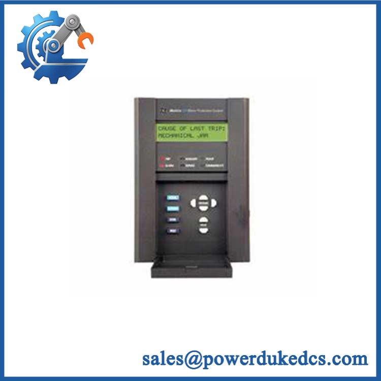
A motor trip is expensive when the relay is no longer available and the replacement is selected from an incomplete part description. The GE Multilin 239 is a dedicated motor protection relay designed to monitor three-phase motor operating conditions and initiate protective action when configured limits are exceeded. Its protection architecture addresses common motor faults including overload, phase loss, phase reversal, current imbalance, undercurrent, locked rotor, and ground-fault conditions.
The relay’s value is in combining motor thermal modeling with electrical-condition monitoring rather than relying on a simple overload contactor. The CT input configuration must match the installed system, with 1 A or 5 A secondary current arrangements available depending on the exact relay configuration. Settings such as motor full-load current, service factor, acceleration time, thermal capacity, and trip thresholds must be restored correctly after replacement. —A relay that powers up and displays normal status can still be incorrectly configured for the motor.
GE Multilin 239
Module 4: Application Scenarios & Field Realities
- On pumps and centrifugal loads, the 239 can provide protection against overload, phase loss, and undercurrent conditions. Undercurrent is particularly useful where a loss of process load can indicate a dry-running pump or broken coupling.
- For compressors and high-inertia motors, locked-rotor and acceleration-related settings deserve careful attention. The relay must distinguish a legitimate long acceleration period from a stalled motor; copying settings from a smaller motor can cause nuisance trips or inadequate protection.
- In conveyors, fans, and material-handling equipment, phase imbalance and thermal protection can help identify abnormal loading before winding temperature reaches a damaging level. Check the CT ratio and phase wiring during commissioning.
- During replacement of an obsolete motor relay, preserve the original protection settings before disconnecting the existing unit. Motor FLA, CT ratio, trip class, thermal capacity, acceleration time, and auxiliary output assignments should be documented rather than reconstructed from memory.
Module 5: Migration, Compatibility & Installation Traps
Replacement Matrix
| Replacement Type | Assessment | Engineering Requirement |
|---|---|---|
| Drop-in Replacement | Potentially yes for an identical Multilin 239 configuration | Match complete catalogue/order code, CT configuration, control power, terminals, and firmware |
| Software Compatible | Configuration-dependent | Restore motor protection settings, communication parameters, alarms, and output assignments |
| Hardware Modification Required | Potentially required for a different relay generation | Verify panel cutout, terminal arrangement, wiring, and auxiliary-control architecture |
Field Traps — Watch Out
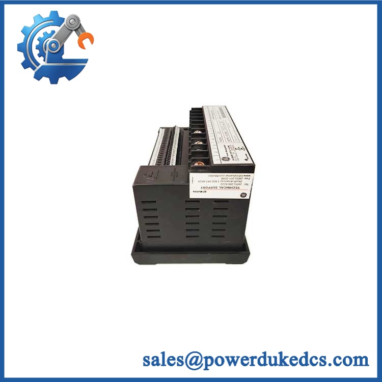
1. The “239” designation alone is incomplete: GE Multilin 239 relays were supplied in different configurations. Verify the complete nameplate/order code before selecting a replacement, particularly control power, CT arrangement, communications, and option codes.
2. CT wiring: Confirm whether the installation uses 1 A or 5 A CT secondaries. Never disconnect an energized CT secondary circuit while the primary conductor is carrying current. Use the site’s approved CT shorting procedure before changing relay wiring.
3. Motor settings are application-specific: Do not copy generic overload or thermal settings into a replacement relay. Motor FLA, service factor, acceleration time, thermal capacity, and starting characteristics should come from the motor documentation and existing protection study.
4. Phase sequence: After wiring, verify phase rotation and current-channel correspondence. Reversed phase sequence or swapped CT inputs can produce incorrect protection decisions even though the relay reports healthy hardware.
GE Multilin 239
Module 6: Quality Assurance SOP
Before shipment, each GE Multilin 239 should undergo a documented inspection sequence appropriate to the available GE relay test equipment.
- Step 1 — Part-number verification: Record the complete Multilin 239 catalogue/order code, serial number, hardware revision, firmware revision, control-power rating, and CT configuration.
- Step 2 — OEM anti-counterfeit visual inspection: Inspect GE Multilin labels, front-panel markings, display, keypad, terminal blocks, communication ports, PCB markings, and manufacturing identifiers. Photograph the complete nameplate.
- Step 3 — Physical condition inspection: Check the enclosure, display, keypad, terminals, connectors, mounting hardware, and PCB for corrosion, contamination, cracked components, damaged terminals, loose hardware, or evidence of previous repair.
- Step 4 — Control-power verification: Confirm the exact auxiliary/control-power requirement from the relay nameplate before energizing the unit. Measure the applied voltage at the test fixture.
- Step 5 — Power-on self-test (POST): Energize the relay under controlled conditions and verify display initialization, status indicators, keypad operation, diagnostic messages, and absence of unexpected hardware alarms.
- Step 6 — Current-input verification: Apply calibrated current signals to the appropriate CT inputs and verify phase-current measurement and scaling. Confirm the configured CT ratio against the test setup.
- Step 7 — Protection-function verification: Use a relay test set to exercise representative overload, phase-loss, current-imbalance, undercurrent, and ground-fault functions where supported by the exact configuration.
- Step 8 — Output verification: Test representative trip, alarm, and auxiliary relay outputs. Confirm contact operation and terminal assignments against the configuration record.
- Step 9 — Communication handshake verification: Where RS485 communication is fitted, verify communication with the appropriate test device and confirm that representative relay measurements and status information can be read.
- Step 10 — Configuration record: Record all tested protection settings and firmware information. Do not overwrite customer-specific settings unless explicitly authorized.
- Step 11 — Final photographic record: Photograph the complete relay, nameplate, serial number, terminal area, display, and final packaging.
QA release criterion: A successful power-up is only a basic hardware check. A fully tested Multilin 239 should have documented electrical-input, protection-function, output, and communication verification appropriate to its exact configuration. Final motor commissioning should include verification of CT wiring, phase sequence, motor settings, trip logic, and coordination with the upstream protection system.











 Start Chat


