

Description
- Brand: GE / GE Grid Solutions / legacy AREVA
- Full Model Number: MVAX31S1DE0754A
- System/Series Family: GE MVAX Trip Circuit Supervision Relay
- Core Function: Trip circuit supervision for circuit-breaker trip and alarm circuits
- Top 3 Hardcore Specs: 110/125 VDC nominal range; hand-reset flag indication; 3 relay units in MVAX91-size-8 architecture
- Relay Type: MVAX31
- Application: Circuit-breaker trip circuit supervision
- Trip Supply: 110/125 VDC
- Alarm Supply: 110/125 VDC
- External Resistors: 1.5 kΩ alarm circuit; 4.0 kΩ trip circuit
- Key Terminals: 13/14 trip circuit; 21/22 trip supply; 27/28 alarm supply
- Contacts: 1 NO + 2 NC reported for this exact ordering code in field specifications
- Stock Status: New Surplus / Fully Tested Refurbished — verify exact nameplate, relay configuration, and resistor arrangement before shipment
GE’s MVAX service manual identifies the MVAX31 as a trip circuit supervision relay with preclosing supervision. The manual documents 110/125 V configurations and specifies 1.5 kΩ and 4.0 kΩ external resistor values for the alarm and trip circuits, respectively.
Module 3: Commercial-Technical Deep Dive
A breaker can be mechanically healthy and still be unavailable when a trip circuit has an open connection, failed relay coil, or lost DC control supply. The GE MVAX31S1DE0754A is a trip circuit supervision relay designed to monitor the integrity of breaker trip circuitry and associated control supplies. Field documentation identifies this exact ordering code with a 110/125 VDC auxiliary supply, hand-reset operation, and 1 NO + 2 NC contacts, while GE’s own MVAX documentation confirms the MVAX31 function and terminal architecture.
The hard ROI comes from maintaining continuous supervision of a protection-critical circuit rather than discovering the failure only when a breaker is commanded to trip. For the 110/125 V version, GE’s service manual specifies 1.5 kΩ for the alarm-supply circuit and 4.0 kΩ for the trip-supply circuit, with the relay using terminals 13/14, 21/22, and 27/28 in its documented test arrangement. The manual also verifies that MVAX31 units can use a three-relay configuration within the larger MVAX91 size-8 assembly. —The exact resistor arrangement and relay configuration must match the installed scheme; these values are not interchangeable across all MVAX variants.
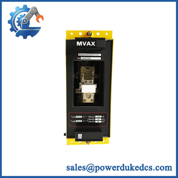
GE MVAX31S1DE0754A
Module 4: Compatibility & Installation Traps
Migration/Compatibility
For a protection panel already specified for MVAX31S1DE0754A, the correct approach is a like-for-like trip circuit supervision relay replacement. No firmware or PLC logic rewrite applies because this is electromechanical supervision hardware rather than a programmable controller.
Exact compatibility still depends on the voltage variant, hand-reset configuration, contact arrangement, external resistor values, terminal wiring, and system role. GE specifically instructs users to verify relay ratings, wiring, DC polarity, and the relevant application diagram before commissioning.
⚠️ Field Traps (Watch Out)
- Resistor value mismatch: For the 110/125 V MVAX21/31/91 family, GE specifies 1.5 kΩ for the alarm circuit and 4.0 kΩ for the trip circuit in the documented configuration. Installing incorrect resistors can alter supervision behavior and produce false alarms or missed faults.
- Trip versus alarm terminal confusion: GE identifies 13/14 for the trip circuit and 27/28 for the alarm supply in the MVAX31 test procedure, with 21/22 also used in the trip-supply path. Verify against the site drawing before reconnecting any conductors.
- Hand-reset indication: The exact S1DE0754A ordering code is associated with hand-reset indication in field documentation. Do not substitute a self-reset version simply because the basic MVAX31 designation matches.
- Energized withdrawal: GE explicitly states that modules must not be inserted or withdrawn while the equipment is energized.
Module 5: Quality Assurance SOP
- OEM anti-counterfeit visual inspection — verify GE/AREVA/Alstom identification, marking, complete MVAX31S1DE0754A code, relay arrangement, flags, terminals, and evidence of unauthorized modification.
- Part-number reconciliation — photograph the complete ordering code, serial number, relay diagram number, and all visible secondary markings.
- Mechanical inspection — inspect the relay case, front plate, handles, captive screws, flags, contacts, push rods, and mounting hardware for impact damage or contamination.
- Voltage/configuration verification — confirm the installed unit is the 110/125 V configuration and matches the customer’s hand-reset/contact arrangement.
- Power-on self-test (POST) — apply controlled DC test voltage and verify expected relay pickup, flag operation, and reset behavior.
- Trip-circuit test — verify the voltage across the documented trip terminals and confirm that the relay responds within the applicable tolerance limits for the 110/125 V configuration.
- Alarm-circuit test — verify alarm-supply behavior and relay operation at the prescribed test points.
- Resistor verification — measure and record the external 1.5 kΩ alarm and 4.0 kΩ trip resistor values where these are part of the customer’s installation.
- Contact-state verification — confirm all applicable NO/NC contacts change state correctly under simulated trip-circuit fault conditions.
- Breaker-simulation test — reproduce the documented open/closed breaker conditions and verify that trip-circuit faults initiate the appropriate supervision alarm without producing an unintended breaker trip.
- Mechanical reset test — verify the hand-reset flag can be operated and restored correctly.
- Insulation verification — perform the manufacturer’s permitted insulation test, using a DC test voltage not exceeding 1000 V and following the approved procedure.
- Final QC release — retain identification photographs, measured resistor values, relay test results, contact-state records, and packaging inspection documentation.
For a trip-circuit supervision relay, the meaningful acceptance evidence is not simply coil continuity. The relay must correctly distinguish normal breaker states from open-circuit supervision faults and provide the intended alarm indication.
Module 6: CRO-Driven Buyer FAQ
1. What is GE MVAX31S1DE0754A?
It is an trip circuit supervision relay used to monitor circuit-breaker trip circuitry. The exact ordering code is documented in field specifications as a 110/125 VDC hand-reset unit, and the family is officially documented by GE as a trip circuit supervision relay with preclosing supervision.
2. What voltage does MVAX31S1DE0754A use?
This exact ordering code is documented in protection-panel specifications as 110/125 VDC. GE’s MVAX manual also provides a dedicated 110/125 V test range and associated tolerance values for .
3. What external resistors are required?
For the documented 110/125 V MVAX21/31/91 configuration, GE specifies 1.5 kΩ in the alarm-supply circuit and 4.0 kΩ in the trip-supply circuit. The actual installed scheme must be checked against the protection drawing before changing either resistor.
4. Can be hot-swapped?
No. GE’s service manual explicitly states that modules and PCB cards must not be inserted or withdrawn while energized. Protection circuits should be isolated according to the approved substation maintenance procedure before replacement.
5. Is obsolete?
The MVAX family is a legacy protection product, and GE currently positions as an alternative for discontinued DBT digital breaker-supervision equipment. That makes exact-part inventory particularly important for existing MVAX installations.
6. What warranty and technical support should I expect?
The quotation should state whether the unit is new surplus, unused, or tested refurbished and specify the warranty duration. Technical support should cover exact ordering-code verification, voltage and resistor configuration, terminal mapping, contact testing, and available commissioning records. Protection-scheme modification, breaker testing, and substation commissioning should remain controlled engineering activities.











 Start Chat


