

Description
-
- Brand: GE
- Full Model Number: PC000087524/01
- System / Series Family: GE Industrial Control — exact platform to be verified
- Core Function: GE control-system printed circuit board assembly identified by part number PC000087524/01
- Top 3 Hardcore Specs: PC000087524 assembly /
/01revision or variant / Application-specific PCB - Part Type: Printed Circuit Board Assembly
- Configuration:
/01variant - Interface / Protocol: Application-dependent; verify from equipment documentation
- Electrical Rating: Application-dependent; do not infer from part number
- Stock Status: New Surplus / Factory Sealed — exact physical condition to be confirmed before quotation
Module 3: Technical Product Introduction
A legacy control-board replacement becomes risky when a part number is treated as a generic PCB identifier rather than an equipment-specific assembly. GE PC000087524/01 is a GE part-numbered control-board assembly, but publicly available technical documentation is insufficient to establish a reliable product family, processor architecture, I/O count, voltage rating, or communications protocol for this exact number. For procurement purposes, the complete
PC000087524/01designation should therefore be preserved rather than shortened toPC000087524.That distinction matters during field replacement. The
/01suffix may identify a specific board configuration, revision, or assembly variant, and the correct interpretation should come from the equipment BOM, GE drawing, nameplate, or existing board documentation. No defensible claim should be made that this board supports Modbus, Ethernet, a particular voltage, or a specific number of I/O channels without evidence from the installed system. —For an obscure legacy GE assembly, accurate identification is more valuable than filling a product page with unverified specifications.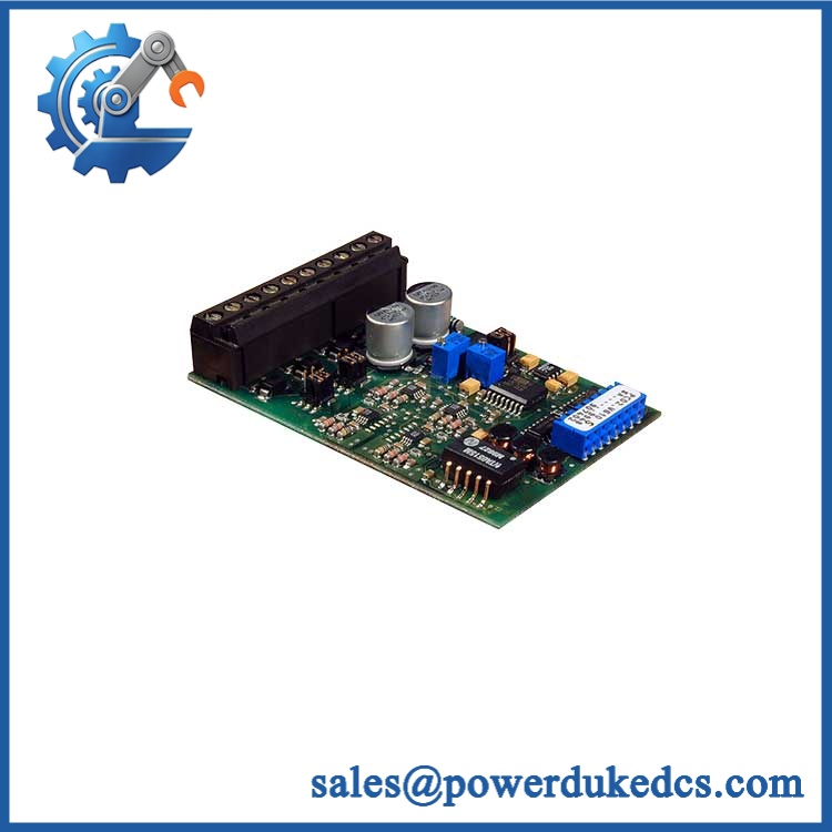
GE 46GE PC000087524/01
Module 4: Application Scenarios & Field Realities
- During a legacy GE control-system outage, the first task should be to photograph the complete PCB label and cabinet location. Include every secondary part number, board revision, connector label, and serial marking before removing the original assembly.
- When the original board is no longer supported, an exact /01 replacement can potentially reduce the scope of the repair because the existing cabinet architecture may remain unchanged. Compatibility still needs to be established against the actual equipment BOM.
- For control cabinets with undocumented field modifications, compare the physical wiring with the latest available schematic rather than assuming the factory drawing remains accurate. Older installations frequently accumulate jumper changes, replacement connectors, and revised wiring.
- When a board has failed repeatedly, inspect the surrounding power supply, field wiring, grounding, cooling, and connected loads before installing another PCB. Replacing the board without correcting the initiating fault can produce another failure immediately after startup.
Module 5: Migration, Compatibility & Installation Traps
Replacement Matrix
Replacement Case Classification Engineering Requirement /01 replacing the identical /01 Drop-in Replacement Verify complete part number, board position, connectors, wiring, and equipment configuration with a different suffix Software Compatible — Verify First Confirm the suffix represents an approved equivalent and verify hardware/configuration differences Similar GE PCB with a different part number Hardware Modification Required Verify electrical interfaces, mounting, signal assignments, and control logic Modern controller replacing /01 Hardware Modification Required Engineer I/O conversion, wiring, software, communications, and commissioning Field Traps — Watch Out
Do not remove the
/01suffix: The complete ordering identifier is . Treat the suffix as part of the procurement specification until the applicable GE documentation explicitly confirms interchangeability.Unknown electrical specification: The part number alone does not establish the board’s supply voltage, current requirements, I/O ratings, or signal levels. Do not energize an unidentified replacement using assumptions derived from another GE PCB.
Connector mapping: Photograph and label every connector before removal. A connector that physically mates with the replacement board does not prove that the underlying signal assignment is identical.
Protocol assumptions: There is insufficient evidence to assign Modbus RTU, Modbus TCP, Ethernet, Profibus, or another protocol specifically to /01. Verify the communication interface from the actual equipment documentation.
Failure-cause investigation: Check the power supply and connected field circuits before commissioning the replacement. Overvoltage, shorted field wiring, grounding faults, and thermal problems can damage a replacement board.
Module 6: Quality Assurance SOP
The pre-shipment inspection for a GE should emphasize exact identification and controlled electrical verification:
- Part-number verification — Confirm the physical marking as and record every visible GE identifier, serial number, revision marking, and PCB assembly code.
- OEM anti-counterfeit visual inspection — Examine GE labels, PCB artwork, component markings, connectors, solder joints, assembly markings, and manufacturing identifiers for inconsistent printing, altered labels, or unauthorized rework.
- Mechanical inspection — Check the PCB substrate, mounting holes, edge contacts, connectors, terminal blocks, heat-affected areas, and accessible components for cracks, deformation, corrosion, contamination, or impact damage.
- Connector inspection — Inspect every connector for bent contacts, damaged housings, contamination, loose pins, oxidation, or evidence of arcing.
- PCB component inspection — Examine capacitors, resistors, ICs, relays, transformers, and other visible components for swelling, cracking, discoloration, overheating, or previous repair work.
- Power-on self-test (POST) — Where the correct GE test fixture and verified electrical specifications are available, power the board under controlled conditions and check applicable status, diagnostic, RUN, or fault indications.
- Circuit-level verification — Test applicable board functions against the equipment-specific GE test procedure. Do not apply assumed input or output levels where the exact electrical specification has not been established.
- Communication handshake verification — If the board incorporates a communication interface, verify the actual interface and protocol from the corresponding GE documentation before performing a handshake test.
- System-interface screening — Where a compatible GE test rack or equipment simulator is available, verify the board’s expected interaction with the associated control architecture.
- Configuration cross-check — Compare the tested /01 with the customer’s supplied nameplate photograph, BOM, wiring information, and original board before dispatch.
- Final inspection and packaging — Photograph the exact part-number label, record inspection and test results, protect connectors and exposed contacts, apply appropriate ESD precautions, and package the board against mechanical shock and moisture.
The final QA record should connect the /01 identification,
/01variant, physical inspection, connector condition, applicable functional tests, configuration verification, and packing record to the exact unit shipped. For this part number, avoiding unsupported technical claims is itself an important part of reliable procurement documentation.











 Start Chat


