

Description
- Brand: GE Multilin
- Full Model Number: SR489-P5-LO-A20-E
- System/Series Family: Multilin 489 Generator Management Relay
- One-Sentence Core Function: Microprocessor-based generator protection, control, metering, diagnostics, and RTD monitoring
- Top 3 Hardcore Specs: 5 A phase CT secondaries; 20–60 VDC or 20–48 VAC control power; four isolated 4–20 mA analog outputs
- Stock Status: New Surplus / Fully Tested Refurbished — final condition verified against the actual unit
Module 3: Commercial-Technical Deep Dive
Generator protection failures become expensive when the replacement relay does not match the original CT, control-power, or analog-output configuration. The SR489-P5-LO-A20-E is a specific 489 order configuration: P5 identifies 5 A phase CT inputs, LO specifies 20–60 VDC or 20–48 VAC control power at 48–62 Hz, A20 provides four 4–20 mA analog outputs, and E adds the enhanced display with the larger LCD and improved keypad. The 489 is designed for synchronous and induction generator protection and management, with six output relays, RTD monitoring, metering, diagnostics, and communications integrated into the relay architecture.
The practical ROI is configuration accuracy, not a marketing claim about speed. A 5 A CT version cannot simply be treated as a 1 A CT version, and applying the wrong control voltage can damage the installed power-supply section. The LO configuration accepts 20–60 VDC or 20–48 VAC; published 489 specifications also identify a maximum power consumption of about 45 VA, with approximately 25 VA typical. Four scalable 4–20 mA transducer outputs can pass measured parameters into a DCS or SCADA system, reducing the need for separate signal-conversion hardware. The relay also supports RTD measurement and event/diagnostic functions, giving maintenance personnel more information after a trip rather than only a binary alarm.
Module 4: Compatibility & Installation Traps
Migration/Compatibility
- Replacement status: The SR489-P5-LO-A20-E is a complete 489 generator management relay configuration, not merely a generic replacement shell. The exact phase CT rating, control-power range, analog-output configuration, and display option must match the installed application.
- Case compatibility: The 489 uses a GE Multilin SR-series drawout arrangement consisting of a removable relay unit and a fixed case. The companion case normally remains wired in the panel.
- Firmware requirement: A same-configuration replacement does not normally imply a control-logic rewrite. Firmware revision should still be recorded before replacement because protection settings and application behavior must be validated after commissioning.
- Important lifecycle note: GE Vernova states that manufacturing for the 489 has been discontinued and identifies the 889 relay as its alternative product path. This makes configuration-accurate legacy replacement important for sites that cannot immediately execute a protection-system migration.
⚠️ Field Traps (Watch Out)
- Control-power mismatch: Do not energize an SR489-P5-LO-A20-E from a HI-range supply. The LO unit is rated for 20–60 VDC or 20–48 VAC, while the HI variant uses a substantially higher voltage range. The manual specifically warns that applied control power must match the installed switching power supply.
- CT circuit handling: The 489 case incorporates automatic CT shorting when the drawout unit is withdrawn, protecting against dangerous open-CT voltage. That does not mean technicians should ignore the manufacturer’s withdrawal procedure. The instruction manual explicitly directs users to turn off control power before drawing out or reinserting the relay to prevent malfunction.
- Case and unit identification: Verify the labels on both the relay and fixed case before installation. GE documentation states that the case label identifies which units can be installed, and custom configurations can have keyed arrangements.
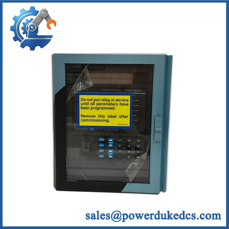
GE SR489-P5-LO-A20-E
Module 5: Quality Assurance SOP
Our pre-shipment inspection for an SR489-P5-LO-A20-E should focus on the relay’s electrical configuration and physical drawout assembly rather than cosmetic appearance alone:
- OEM anti-counterfeit visual inspection — verify GE Multilin identification, 489 family markings, order code, revision data, labels, PCB condition, connectors, display assembly, keypad, and case interface.
- Order-code verification — confirm the exact P5 / LO / A20 / E configuration before release.
- Power-input verification — inspect the power-supply section and, where the test setup permits, apply the correct LO-range control power while monitoring current draw and startup behavior.
- Power-on self-test (POST) — check initialization, display operation, keypad response, status indications, and diagnostic behavior for abnormal ERR or alarm conditions.
- CT and voltage input testing — perform controlled secondary-injection checks appropriate to the available relay test equipment; verify measured values and scaling rather than assuming factory settings.
- RTD verification — simulate supported RTD inputs and confirm temperature measurement channels respond correctly.
- Analog output verification — test the four 4–20 mA outputs across representative values and confirm output scaling and isolation.
- Output relay verification — operate the programmable relay outputs under controlled test conditions and record contact behavior.
- Communication handshake verification — where the installed interface and test environment permit, verify serial communication and the applicable Modbus/DNP communication path.
- Configuration record — capture firmware information, existing protection settings where available, order-code details, test readings, and identification photographs.
- Final ESD packaging — place the tested relay in antistatic protection with mechanical cushioning appropriate for the drawout assembly.
GE documentation identifies a substantially broader functional test program for the 489, including current accuracy, voltage input accuracy, RTD accuracy, digital inputs, analog I/O, output relays, power measurement, reactive power, and protection-function testing.
Module 6: CRO-Driven Buyer FAQ
1. Is the SR489-P5-LO-A20-E obsolete, and can I still source an authentic replacement?
Yes, the 489 is a legacy product. GE Vernova states that manufacturing has been discontinued and directs customers toward the 889 as an alternative. For an immediate legacy replacement, verify the exact order code rather than purchasing a generic “489” description. The P5, LO, A20, and E configuration should match the installed relay.
2. Can the be hot-swapped?
It is a drawout relay with automatic CT-shorting mechanisms in the case, which is specifically intended to prevent dangerous open-CT conditions when the relay is withdrawn. However, the 489 instruction manual explicitly says to turn off control power before drawing out or reinserting the relay. Treat drawout capability as a maintenance feature, not permission to ignore the documented de-energization procedure.
3. What happens if my cabinet supplies 120 VAC?
That is not the correct control-power range for the LO version. The LO configuration is rated for 20–60 VDC or 20–48 VAC. A 120 VAC source belongs to neither range and should not be applied to this relay. Confirm the actual case terminal labeling and power-supply configuration before energization.
4. Does this model include the 4–20 mA outputs and enhanced display?
Yes. The A20 suffix identifies four 4–20 mA analog outputs, while E identifies the enhanced display configuration with a larger LCD and improved keypad. This distinguishes the unit from the corresponding A1 and basic-display configurations.
5. What warranty and technical support should I expect?
Warranty duration should be stated on the quotation for the specific unit supplied. Technical support should cover part-number verification, configuration matching, installation checks, and interpretation of documented pre-shipment test results. It should not be represented as a substitute for generator-protection engineering, relay coordination, CT validation, or site-specific commissioning.











 Start Chat


