

Description
- Brand: GE Multilin
- Full Model Number: SR745-W2-P1-G1-HI-A-L-R-E
- Lifecycle Status: Discontinued / Legacy
- Core Function: Two-winding transformer protection and management relay
- Top 3 Technical Specs: W2 two-winding configuration; P1 1 A phase-current inputs; G1 1 A ground-current inputs
- Control Power: HI — 90–300 VDC; 70–265 VAC at 48–62 Hz
- Options: A analog inputs/outputs; L loss-of-life monitoring; R restricted ground fault
- Display: E enhanced display with larger LCD and two RS485 ports
- Protection Functions: Differential; phase/ground overcurrent; restricted ground fault; overexcitation; frequency; transformer overload
- Communications: RS232; RS485/RS422; Modbus RTU; DNP 3.0 Level 2; Ethernet depends on ordered hardware configuration
- Mounting: Drawout relay case
- Stock & Condition: Physical stock and condition to be confirmed against the specific unit
- Shipping: Emergency dispatch subject to inspection completion and carrier cutoff
The order-code structure above is documented for the 745 Transformer Protection System: W2 identifies two windings, P1 specifies 1 A phase-current inputs, G1 specifies 1 A ground-current inputs, HI identifies the high-voltage control-power range, A/L/R select analog I/O, loss-of-life, and restricted ground-fault options, and E denotes the enhanced display configuration.
Obsolescence & Supply Chain Deep Dive
The main procurement risk with the GE Multilin SR745 is lifecycle exposure rather than a lack of technical capability. GE Vernova identifies the 745 as a legacy product and states that manufacturing has been discontinued, with the 845 presented as the newer alternative. Yet many substations and industrial transformer systems were engineered around the 745’s drawout architecture, protection settings, communications scheme, and existing wiring. Replacing a failed relay with the same full order code can therefore avoid a much larger engineering exercise. The specific SR745-W2-P1-G1-HI-A-L-R-E configuration is particularly important because its code defines the winding arrangement, CT input ratings, control power, and installed options; a similar-looking 745 with different code segments can have materially different electrical characteristics.
From a TCO perspective, a verified legacy relay can be less disruptive than accelerating an entire protection-system migration. The 745 combines transformer differential protection, overcurrent protection, restricted ground fault, overexcitation, frequency functions, thermal/overload protection, metering, event recording, waveform capture, and transformer aging or loss-of-life monitoring in one device. GE also documents drawout construction specifically to reduce maintenance intervention time. Keeping the existing relay architecture can mean less panel modification, less field rewiring, less relay-setting redevelopment, and less commissioning effort (although the cost case depends heavily on the installed protection scheme and engineering requirements).
Compatibility & Replacement Matrix
| Replacement Scenario | Classification | Engineering / Procurement Action | Estimated Switch Effort |
|---|---|---|---|
| Same SR745-W2-P1-G1-HI-A-L-R-E replacing the identical failed relay | Drop-in Replacement | Match complete order code, hardware revision, control power, CT ratings, options, and case configuration | 1–2 hours for relay changeout plus testing |
| Same 745 family with a different option code | Conditional Compatibility | Compare CT ratings, winding configuration, option set, display/communications hardware, and settings | 2–6 hours engineering review |
| Another SR745 with different P or G current rating | Not automatically compatible | Verify transformer CT secondary ratings before energization | 4–8+ hours |
| SR745 replaced by GE 845 | Hardware Modification | Review panel dimensions, terminals, wiring, settings, communications, protection logic, and commissioning | 1–3+ engineering days |
| replaced by a non-GE relay | Hardware Modification | Rebuild protection philosophy, I/O mapping, communications, wiring, and test procedures | Several engineering days to multiple weeks |
Field Traps (Watch Out)
CT Rating Mismatch: The P1 and G1 code segments are not cosmetic. P1 specifies 1 A phase-current inputs, while G1 specifies 1 A ground-current inputs. Installing a relay with a different current-input code without checking the transformer CT secondaries can produce an invalid protection configuration.
Control Power and Option Mismatch: HI specifies the high-control-power version, while A, L, and R add analog I/O, loss-of-life monitoring, and restricted ground fault. The replacement should match the actual functions used in the installed scheme. The E suffix also matters because the enhanced-display configuration differs from the basic display version and includes two RS485 ports.
Case Compatibility: The 745 is a drawout design. GE’s documentation states that a 745 relay can be installed in a 745 case but not in the case of another SR-series product. Do not approve a physical substitute based solely on enclosure appearance.
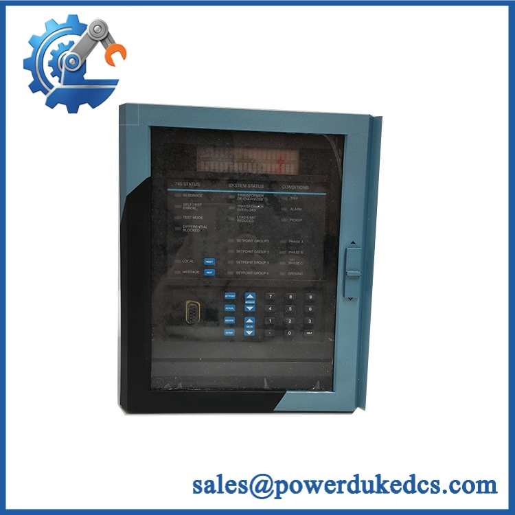
GE SR745-W2-P1-G1-HI-A-L-R-E
Quality Assurance & Testing SOP
Incoming Identity Control: Record the complete -W2-P1-G1-HI-A-L-R-E order code, serial number, hardware revision, front-panel configuration, connector arrangement, and visible manufacturing markings.
OEM Anti-Counterfeit Visual Inspection: Compare GE/Multilin markings, display assembly, keypad, rear connectors, PCB construction, labels, screws, board revision information, and component placement against available 745 reference material. Any unexplained discrepancy places the unit on QA hold.
Mechanical Inspection: Check the drawout mechanism, card guides, terminals, rear connectors, locking hardware, display window, keypad, and case interface for damage, corrosion, deformation, contamination, or evidence of unauthorized rework.
Power-On Self-Test: Install the relay in an approved 745 test case and apply the correct control-power range for the HI configuration. Record startup behavior, self-test results, display operation, status indicators, diagnostic messages, and any reported configuration faults. The 745 documentation specifically uses self-test status and diagnostic indications during startup.
Protection-Function Test: Verify representative differential, phase overcurrent, ground overcurrent, restricted ground fault, frequency, overexcitation, and overload elements against controlled test values. Record pickup, timing, trip logic, and alarm outputs according to the intended setting file.
Analog I/O Test: Because this unit includes the A option, exercise the installed analog inputs and outputs and compare measured values against the configured ranges.
Loss-of-Life Verification: Because L is specified, verify that transformer aging/loss-of-life calculations and associated data points initialize and report correctly within the test environment.
RS485 Communications Test: Confirm local and remote serial communications, addressing, baud rate, protocol response, and stable data exchange. GE documentation identifies RS232 and RS485/RS422 communication interfaces on the 745 platform.
Configuration Verification: Compare transformer winding configuration, CT ratios, protection settings, logic assignments, communications parameters, and installed options against the approved baseline before shipment.
Extended Run Test: Operate the relay continuously under a representative protection-test sequence and monitor resets, diagnostic alarms, communication interruptions, unstable measurements, and abnormal temperature behavior.
Final QA Record: Archive the exact order code, serial number, revision data, inspection photographs, test records, configuration backup, and packaging condition.
Procurement & Lifecycle FAQ
Is the GE -W2-P1-G1-HI-A-L-R-E genuinely in stock, and what is the emergency-shipping cutoff?
Stock should be confirmed from the physical inventory lot before PO release. For an emergency requirement, obtain confirmation of the exact order code, serial number, inspection status, packing readiness, and same-day carrier cutoff.
How do you verify the condition and authenticity of a discontinued ?
Verification should cover the complete order code, GE/Multilin markings, serial information, hardware revision, connectors, drawout mechanism, display configuration, and functional test results. Appearance alone is not sufficient for a protection relay.
Are there firmware or software compatibility issues engineers should check before issuing the PO?
Yes. The 745 family has firmware-dependent software integrations. GE documentation for its PMCS environment lists specific supported firmware revisions, demonstrating that communications software should not be assumed to work identically with every relay revision. Confirm the installed relay firmware, EnerVista/745 software environment, SCADA protocol, and site communications requirements before release.
Is the -W2-P1-G1-HI-A-L-R-E a direct replacement for other versions?
Only after the complete order code is matched. W2, P1, G1, HI, A, L, R, and E each define meaningful hardware or functional characteristics. A relay with a different CT input rating, control-power range, option set, or display/communications configuration should not be treated as an unconditional substitute.
What warranty and return terms apply?
The quotation for the specific relay should state the warranty duration, DOA coverage, RMA procedure, return window, and replacement or refund terms. For transformer protection equipment, procurement should also retain the relay’s serial number and final test record as part of the receiving documentation.











 Start Chat


