

Description
- Brand: GE Multilin
- Full Model Number: SR750-P5-G1-S1-HI-A20-R
- Product: 750 Feeder Management Relay
- Lifecycle Status: Legacy / Obsolete status should be verified
- Core Function: Feeder protection, control, metering, and monitoring
- Phase CT Input: 5 A
- Ground CT Input: 1 A
- Control Power: HI high-range supply
- Analog Outputs: 4–20 mA
- Communications: Ethernet option; serial communications also available within the 750 architecture
- Protection: Overcurrent, voltage, frequency, directional, breaker failure, and feeder-specific protection functions
- Front Panel: Enhanced relay interface with display and keypad
- Stock & Condition: Physical stock and condition to be confirmed per quotation; New Surplus or Tested Refurbished where available
- Supply Mode: Direct industrial spare-parts supply; emergency dispatch subject to confirmed inventory and carrier cutoff
Obsolescence & Supply Chain Deep Dive
When a legacy feeder relay fails, replacing only the protection hardware can be considerably less disruptive than redesigning the feeder panel around a different relay platform. The GE Multilin 750 is a feeder management relay designed for protection, control, metering, and monitoring applications. The SR750 ordering architecture distinguishes CT input, communications, control-power, analog-output, and front-panel options, making the complete order code important when sourcing an exact replacement rather than simply matching the “SR750” family name.
For TCO analysis, an exact or properly configured SR750 replacement can preserve existing CT wiring, control circuits, trip logic, metering architecture, and plant communications. That can avoid the engineering and commissioning costs associated with a complete relay migration. The P5-G1-S1-HI-A20-R suffix should be verified against the installed relay before procurement approval, particularly the CT configuration, communications options, control-power range, analog-output configuration, and front-panel/revision information (older inventory can contain different hardware or firmware revisions).
Compatibility & Replacement Matrix
| Replacement Scenario | Assessment | Engineering / Procurement Guidance | Estimated Switch Time |
|---|---|---|---|
| Identical SR750-P5-G1-S1-HI-A20-R replacement | Drop-in Replacement subject to configuration verification | Match the complete order code, terminal arrangement, firmware, and protection settings | Approx. 2–6 hours |
| Same SR750 family with different firmware | Software Compatible — verification required | Compare firmware, settings, communications, and option configuration | Approx. 4–8 hours |
| Same family with different CT or communication options | Not automatically interchangeable | Verify CT inputs, network interfaces, and installed wiring before installation | Approx. 4–8 hours |
| Different feeder relay platform | Hardware Modification | Requires CT/VT, I/O, communications, settings, panel, and commissioning review | Several days to several weeks |
Field Traps — Watch Out
- Complete order-code mismatch: Do not approve an replacement solely from the family number. P5, G1, S1, HI, A20, and R option codes need to be checked against the installed unit.
- CT configuration: Verify both phase and ground CT arrangements before energization. A mismatch can produce incorrect metering or protection behavior.
- Communications: Confirm the installed Ethernet/serial architecture and the plant SCADA configuration before substituting another option package.
- Analog-output scaling: If the existing feeder relay sends 4–20 mA signals to a DCS or PLC, verify channel assignments and scaling after replacement.
Quality Assurance & Testing SOP
The should be treated as a protection and control device, not simply as a communications or metering module. Pre-shipment testing should cover identification, power-up, measurement, I/O, communications, and applicable protection functions.
- OEM anti-counterfeit visual inspection: Verify GE Multilin markings, identification, complete model code, labels, connectors, front-panel construction, and visible PCB details.
- Nameplate verification: Record the complete -P5-G1-S1-HI-A20-R designation, serial number, hardware revision, firmware information, and manufacturing data where available.
- Mechanical inspection: Check the enclosure, terminal blocks, front-panel keypad/display, connectors, mounting mechanism, and PCB assembly for physical damage or unauthorized modification.
- Power-on self-test (POST): Energize the relay using the appropriate control-power range and verify startup diagnostics, display initialization, status LEDs, and diagnostic messages.
- Display/keypad testing: Verify the front-panel display, navigation keys, alarm/status indication, and local control functions.
- CT input simulation: Apply calibrated current signals to applicable phase and ground inputs and verify measurement and phase identification.
- Voltage input testing: Where applicable, inject controlled voltage signals and verify measurement and configured protection responses.
- Protection-function testing: Test applicable overcurrent, ground fault, voltage, frequency, directional, breaker-failure, and feeder protection elements against the approved test plan.
- Digital I/O load testing: Exercise applicable digital inputs and output contacts under controlled conditions.
- 4–20 mA output testing: Verify each configured analog output with calibrated measurement equipment and confirm expected scaling.
- Ethernet/serial communication test: Verify the applicable communication interface and stable data exchange with the approved test environment.
- Event and alarm verification: Generate representative alarm/trip conditions and confirm correct event recording and indication.
- Extended run test: Monitor the relay during controlled operation for intermittent resets, abnormal heating, communication loss, or diagnostic faults.
- Final traceability: Photograph the actual relay, record serial/firmware information, document test results, and retain the inspection record.
- ESD-safe packaging: Package the relay against electrostatic discharge, shock, vibration, and moisture.
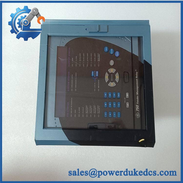
GE SR750-P5-G1-S1-HI-A20-R
Procurement & Lifecycle FAQ
Is the GE -P5-G1-S1-HI-A20-R genuinely in stock, and what is the cutoff for emergency shipping?
Physical inventory should be confirmed before the PO is accepted. For emergency requirements, provide the required quantity and destination so the actual unit, condition, test status, and carrier cutoff can be confirmed before dispatch.
How do you verify the condition and authenticity of a surplus ?
The unit should undergo complete model-code verification, nameplate inspection, physical examination, controlled power-up, display/keypad testing, CT/VT simulation, digital I/O testing, 4–20 mA output testing, communications testing, and applicable protection-function testing.
Can any replace -P5-G1-S1-HI-A20-R?
No. The complete order code should be matched before procurement approval. CT configuration, communications options, control-power range, analog outputs, and hardware/firmware information can affect interchangeability.
Are there firmware or configuration issues my engineers should check before issuing the PO?
Yes. Export or document the existing relay configuration before removal whenever possible. Check firmware, protection settings, CT/VT ratios, trip logic, digital I/O assignments, analog-output scaling, communications parameters, and SCADA mapping before commissioning.
What warranty and return terms apply?
Warranty duration, return eligibility, and exclusions should be stated on the quotation according to the actual unit condition and testing status. These terms should be confirmed in writing before the PO is issued.











 Start Chat


