

Description
- Brand: GE General Electric
- Full Model Number: TP1616SS
- System/Series Family: Power Break I
- Core Function: 1600A low-voltage insulated-case circuit breaker for high-current distribution protection and switching
- Top 3 Hardcore Specs: 1600A rating | 600 VAC frame rating | 65 kA interrupting rating at 480 VAC
- Configuration: 3-pole | 3-phase | Bolt-on mounting
- Trip Arrangement: Electronic trip configurations vary by supplied assembly
- Stock Status: New Surplus — stock confirmation required
Technical Product Introduction
A failed 1600A main breaker can take an entire switchboard section offline, particularly when the device sits upstream of MCCs, process loads, or plant utility feeders. The GE TP1616SS belongs to the Power Break I insulated-case breaker family and is specified for 1600A service at up to 600 VAC, with published configurations showing 65 kA interrupting capability at 480 VAC. Three-pole construction makes it suitable for three-phase distribution duties where the breaker must both carry substantial continuous current and interrupt a high prospective fault current.
The practical value here is capacity, fault-duty margin, and a known physical platform rather than PLC-style processing performance. A 1600A frame is intended for larger distribution applications than common 400A, 600A, or 800A feeder devices, reducing the need to split a single high-current circuit across multiple breaker frames. The exact trip unit matters, though: documented TP1616SS listings show different trip-unit configurations, including RMS-9 and Micro VersaTrip Plus versions, so the nameplate and trip-unit identification must be checked before procurement.
Application Scenarios & Field Realities
- At a plant main switchboard, the TP1616SS can serve as a high-current incoming or feeder breaker where the available fault current requires more than a standard molded-case device can provide. Coordination studies should be reviewed against the actual trip-unit settings before energization.
- Inside large MCC lineups, a 1600A breaker may protect a major motor-control section or a concentrated group of downstream feeders. The important field check is not only the ampere rating; bus connection geometry, breaker mounting, and the available interrupting rating must all match the existing gear.
- For process utility distribution, such as large pumping, blower, chiller, or compressor systems, the breaker can sit upstream of substantial three-phase loads. During replacement work, confirm that the replacement device preserves the intended short-circuit rating at the system voltage rather than comparing amperage alone.
- On legacy GE Power Break installations, maintaining the same breaker family can reduce mechanical rework, but only when the replacement matches the installed configuration. A TP1616SS with a different trip unit or mounting arrangement should not be treated as interchangeable just because the catalog number appears similar.
Migration, Compatibility & Installation Traps
Replacement Matrix
| Replacement Condition | Classification | Engineering Requirement |
|---|---|---|
| Existing breaker is an identical TP1616SS with matching pole count, mounting, voltage class, and trip-unit configuration | Conditional Drop-in Replacement | Verify nameplate, mechanical interface, bus connection, and trip settings before installation |
| Same GE Power Break family but different trip unit or electrical configuration | Software/Settings Compatible only in limited cases | Compare trip-unit functions, ratings, accessories, and protection settings; do not assume direct interchangeability |
| Different breaker frame, mounting arrangement, bus connection, or switchgear envelope | Hardware Modification Required | Mechanical adaptation or switchgear engineering review is required |
Field Traps — Watch Out
Trip-unit mismatch: assemblies can appear externally similar while carrying different trip-unit configurations. Published examples include RMS-9 and Micro VersaTrip Plus arrangements. Replacing one without confirming long-time, short-time, instantaneous, and ground-fault functions can change the protection scheme.
Mounting and bus interface: Bolt-on installation is part of the published configuration, but the complete switchgear interface still has to be checked. Do not force a breaker into the compartment when alignment, primary connections, or secondary accessory plugs do not match (a mechanical fit is not proof of electrical compatibility).
Before removal or insertion, follow the switchgear manufacturer’s isolation, lockout/tagout, discharge, and arc-flash procedures. For a 1600A distribution device, installation should be treated as switchgear work, not a routine control-module swap.
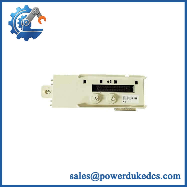
GE TP1616SS
Quality Assurance SOP
Receiving inspection: Record the catalog number as and compare the breaker nameplate, molded markings, pole configuration, voltage class, ampere rating, and trip-unit identification against the purchase specification.
OEM anti-counterfeit visual inspection: Examine the enclosure molding, labels, terminal markings, hardware, warning labels, and manufacturer identification for inconsistent fonts, altered markings, damaged overlays, or evidence of rework. Serial and manufacturing information are recorded where available.
Mechanical inspection: Verify pole alignment, operating mechanism movement, handle travel, mounting points, primary connection condition, and visible insulation surfaces. No cracked housing, loose hardware, severe corrosion, or burned contact areas should be accepted.
Electrical condition check: Where test capability and the supplied configuration permit, perform continuity verification and insulation-resistance checks appropriate to the breaker assembly and trip unit. Test limits should follow the applicable GE/ABB documentation and site electrical-safety procedures.
Power-on self-test (POST): This terminology applies only to variants fitted with electronic trip units or monitoring electronics. The base breaker itself is not a PLC and does not use a universal RUN/ERR LED sequence. For an electronic trip unit, verify that its available display or status indicators initialize normally and show no diagnostic fault.
Communication handshake verification: Not applicable to the basic mechanical breaker assembly. When the installed electronic trip unit includes a communication interface, verify the local communication path, device addressing, and a successful readback of available status or metering data before shipment or commissioning.
Final functional review: Confirm breaker open/close operation, accessory configuration, trip-unit identity, and nameplate data against the order record. Photograph the identification plate and external condition as part of the pre-shipment QA file.
Packing release: Use mechanical protection around handles, terminals, and exposed connection points; secure the operating mechanism against shipping damage; and retain inspection records with the unit serial or internal asset reference.











 Start Chat


