

Description
- Brand: GE Multilin
- Full Model Number: UR6TH / UR-6TH
- System/Series Family: Multilin Universal Relay UR Series
- Core Function: Digital input/output expansion for protection relay monitoring and control
- Top 3 Hardcore Specs: 8 contact inputs; 4 Form-A outputs; Form-A output response under 4 ms
- Stock Status: New Surplus — stock confirmation required
Technical Product Introduction
When a UR-series protection relay loses a discrete I/O channel, the problem is rarely limited to the card itself. Breaker status, interlocks, alarms, trip commands, and auxiliary control circuits may all depend on those points. The GE UR6TH is identified as a digital I/O expansion module for the Multilin Universal Relay platform, with published product information specifying eight contact inputs and four Form-A outputs. The Form-A outputs are specified for response below 4 ms, making the module suitable for fast discrete control functions when the host relay configuration supports the required logic. The UR family itself uses a modular architecture with expandable I/O and programmable FlexLogic functions.
For replacement planning, the important distinction is that UR6TH is an I/O hardware component rather than a standalone protection relay. Its behavior is determined by the host UR relay, firmware, configuration, terminal assignment, and FlexLogic scheme. The broader UR platform supports configurable digital inputs with recognition times below 1 ms, selectable input thresholds, and programmable debounce settings; these specifications apply to the UR platform and should not automatically be assigned to every UR6TH configuration. A direct replacement therefore requires an order-code and wiring comparison before installation — physical fit alone is not sufficient.
Application Scenarios & Field Realities
- Breaker control and status feedback: In a substation panel, the input channels can be used for discrete signals such as breaker auxiliary contacts, local/remote status, lockout indication, and interlocking conditions. The four Form-A outputs can provide relay-controlled commands where the host configuration assigns those points accordingly.
- Motor and feeder protection panels: A UR relay may need several independent discrete signals around the protected feeder or motor. Start permissive, breaker position, trip circuit supervision, external blocking, and alarm contacts can consume I/O quickly. An additional I/O module can avoid redesigning the complete relay panel when the host hardware supports the module.
- Transformer and generator protection: For larger protection schemes, digital signals often originate from auxiliary relays, lockout devices, breaker mechanisms, and plant control systems. The UR platform supports generator, transformer, transmission, distribution, and motor protection applications, with programmable logic used to coordinate protection and control functions.
- Existing UR relay maintenance: During a forced-maintenance window, the practical objective is to restore the original I/O architecture without changing the protection philosophy. Record the existing terminal wiring, module position, relay order code, firmware information, and FlexLogic assignments before removing the failed hardware. One overlooked input assignment can produce a commissioning fault even when the replacement card itself is electrically sound.
Migration, Compatibility & Installation Traps
Replacement Matrix
| Replacement Type | Assessment | Engineering Requirement |
|---|---|---|
| Drop-in Replacement | Conditionally applicable | Confirm the existing UR relay, module position, order code, I/O configuration, and hardware revision |
| Software Compatible | Configuration verification required | Check FlexLogic assignments, input mapping, output logic, and relay firmware |
| Hardware Modification Required | Normally not required for a correctly matched UR6TH | Avoid terminal rewiring unless the original and replacement configurations have been formally compared |
Field Traps — Watch Out
I/O configuration mismatch: Do not select UR6TH based only on the fact that it belongs to the UR family. Published information identifies the as an eight-input/four-Form-A-output module, while the UR family contains multiple I/O configurations. Verify the exact module designation against the existing hardware before purchase.
FlexLogic point mapping: A replacement module can be electrically correct while the application logic remains incorrect. Export or record the existing relay settings before intervention. After installation, verify each affected digital input, output command, interlock, alarm, and trip path individually.
Contact-input voltage: GE’s UR-family specifications distinguish dry-contact and wet-contact inputs and provide selectable thresholds of 17 V, 33 V, 84 V, and 166 V, with wet-contact inputs specified up to 300 V DC. These are platform-level specifications, so the actual installation must be checked against the module’s applicable hardware configuration and the host relay documentation.
Output circuit verification: Form-A outputs are normally-open contacts. Confirm common and normally-open terminal assignments before energizing the control circuit. For trip or breaker-control applications, perform a point-to-point check with the equipment isolated before allowing an actual command to reach the field device.
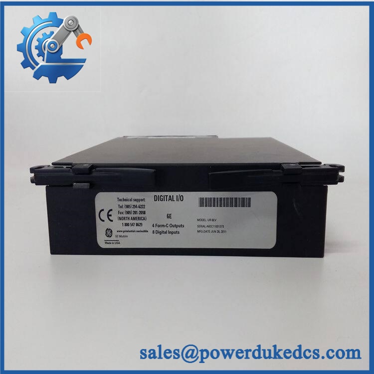
GE UR6TH
Quality Assurance SOP
Every available unit should pass a documented inspection sequence before shipment:
- OEM anti-counterfeit visual inspection: Check GE/Multilin identification, model marking, labels, connector construction, PCB condition, manufacturing markings, and overall assembly against known UR-series hardware references.
- Part-number verification: Confirm the physical marking corresponds to and reconcile the identification with the sales order.
- Mechanical inspection: Examine connectors, terminal interfaces, mounting points, PCB surfaces, housings, and retaining hardware for impact damage, corrosion, contamination, bent contacts, or unauthorized modification.
- Digital-input verification: On an available compatible UR test assembly, exercise the eight contact-input channels and confirm that the host relay recognizes the expected state changes.
- Digital-output verification: Test the four Form-A outputs where the available test fixture supports the required load and relay configuration.
- Response verification: Where test equipment permits, verify the output operating response against the applicable technical specification; published information identifies a response below 4 ms for its Form-A outputs.
- Power-on self-test (POST): On a compatible host relay, monitor startup behavior and verify expected ERR/RUN indications before releasing the module.
- Communication handshake verification: Confirm that the host relay recognizes the installed I/O hardware and that the relevant I/O points are available through the relay configuration software.
- FlexLogic verification: Check affected logic equations, input states, output commands, interlocks, and alarms against the saved configuration.
- Final inspection: Record model number, identification markings, physical condition, test results, packaging condition, and inspection status before shipment.
Procurement note: should be purchased against the complete host-relay configuration rather than as a generic UR-series card. Before installation, verify the host relay model, complete order code, module position, firmware revision, I/O allocation, terminal wiring, and FlexLogic configuration. The GE UR platform is modular, but individual I/O arrangements are configuration-dependent.











 Start Chat


