

Description
- Brand: GE Multilin
- Full Model Number: UR8NH / UR-8NH
- Lifecycle Status: Legacy / Obsolescence-Risk — verify current OEM availability
- Core Function: CT/VT AC signal acquisition for GE Multilin Universal Relays
- Top 3 Technical Specs: 8 CT channels; 1A/5A secondary input; 50/60 Hz
- Stock & Condition: New surplus / tested refurbished — confirm exact unit condition before PO
The UR8NH is identified as the GE Multilin UR Series 8N CT/VT module, with six phase CT inputs and two ground CT inputs, supporting 1 A or 5 A secondary signals.
Module 3: Obsolescence & Supply Chain Deep Dive
A failed CT/VT module inside an operating GE Multilin Universal Relay can turn a relatively small hardware fault into a protection-system availability problem. The UR8NH provides the eight-current-input architecture required by the 8N configuration, including six phase CT channels and two ground CT channels. For maintenance teams supporting installed UR-series equipment, locating a matching module can therefore be preferable to waiting for a longer factory sourcing cycle or redesigning an operating protection panel. The module supports 1 A and 5 A CT secondary inputs and 50/60 Hz operation.
From a TCO standpoint, replacing the failed module is often a smaller intervention than migrating an entire protection system. Existing relay hardware, wiring, panel engineering, commissioning records, and protection logic may remain substantially unchanged. That can reduce engineering hours, outage exposure, testing requirements, and spare-parts requalification costs. The key caveat is compatibility: UR8NH should be matched against the installed relay’s complete configuration and hardware order code before purchase (especially CT/VT configuration and firmware requirements). Surplus stock can also remove a factory lead-time constraint when an exact legacy module is available.
Module 4: Compatibility & Replacement Matrix
| Procurement Check | UR8NH Assessment | Engineering Action |
|---|---|---|
| Replacement Type | Drop-in hardware replacement when the existing relay is configured for UR8NH / 8N | Confirm relay order code and module designation before PO |
| Software Compatibility | Configuration-dependent | Verify relay firmware and EnerVista project compatibility before commissioning |
| Hardware Modification | Normally not required for a matching 8N module | Do not assume interchangeability with other UR CT/VT module variants |
| Typical Switch Time | Approx. 2–6 hours for controlled replacement and verification | Allow additional outage time for protection testing |
| Engineering / Commissioning Cost | Approx. 500–2,000 depending on site labor and testing scope | Include relay functional testing and protection verification |
| Major Upgrade Alternative | Full relay/system migration | Higher engineering, commissioning, documentation, and outage cost |
Field Traps — Watch Out
CT/VT Configuration: UR modules are not interchangeable merely because they physically belong to the same UR family. The 8N configuration is associated with six phase CT channels plus two ground CT channels; confirm that this matches the failed module and the relay’s order code.
Firmware / Configuration Mismatch: Do not install the spare and immediately return the protection system to service. Record the existing relay firmware, module identification, settings, wiring, and CT ratios first, then verify the replacement through the relay’s diagnostics and functional protection tests. The UR platform performs startup health diagnostics and ongoing hardware monitoring.
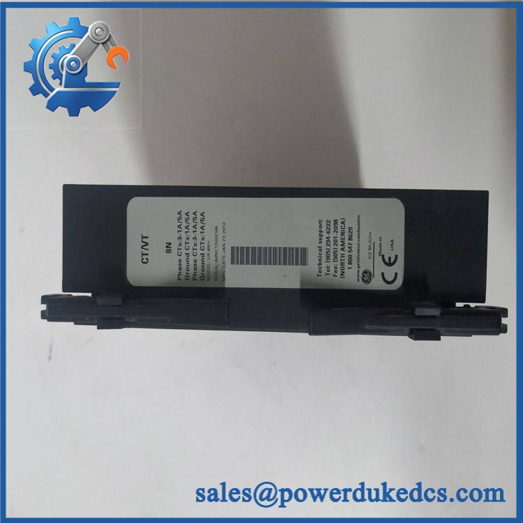
GE UR8NH
Module 5: Quality Assurance & Testing SOP
Every surplus or refurbished should be treated as a protection-system component, not ordinary warehouse stock.
1. Incoming inspection
- Record manufacturer, model, serial number, and nameplate data.
- Perform OEM anti-counterfeit visual inspection.
- Inspect PCB surfaces, connectors, terminals, mounting hardware, and enclosure.
- Check for corrosion, contamination, cracked components, bent pins, or evidence of rework.
2. Configuration verification
- Confirm identification.
- Verify the module configuration against the purchase specification.
- Record CT input arrangement and applicable 1 A / 5 A ratings.
- Photograph identification markings for the shipment record.
3. Power and diagnostic testing
- Install the module on a compatible UR test platform.
- Apply the specified system power under controlled conditions.
- Perform power-on self-test (POST) and check the relay diagnostic status and ERR/RUN LED indications.
- Review internal diagnostic messages for hardware or signal-integrity faults.
4. Signal and I/O testing
- Apply controlled simulated CT signals to applicable input channels.
- Verify measurement response across all required channels.
- Perform ground-input verification where applicable.
- Conduct I/O load testing where the installed relay configuration requires associated protection/control outputs.
5. Final QC
- Compare measured results with the applicable test limits.
- Record firmware/configuration information from the host relay.
- Generate a test report with serial number and test date.
- Package using ESD protection, cushioning, and moisture protection.
- Apply a QC-passed identification label before shipment.
Module 6: Procurement & Lifecycle FAQ
Is the GE genuinely available, and what is the emergency-shipping cutoff?
Stock status must be confirmed against the specific serial-numbered unit before the PO is released. For emergency requirements, the practical cutoff depends on warehouse location, payment clearance, inspection status, and courier pickup. Same-day shipment is possible only when the requested unit has already passed final QC and cleared order processing.
How do you verify authenticity and condition for an obsolete or surplus ?
The unit should undergo nameplate and serial-number inspection, physical PCB and connector inspection, configuration verification, and powered diagnostic testing. The seller should provide actual unit photos and the test record for the supplied serial number. Do not accept “new” as sufficient evidence without traceable inspection records.
Could firmware compatibility cause problems after installation?
Yes. The is a hardware module within a configured GE Multilin UR relay, so the host relay’s hardware order code, firmware, CT/VT configuration, and protection settings should be checked before installation. Startup diagnostics should be completed before the relay is returned to service.
Is the a direct replacement for every GE Multilin UR CT/VT module?
No. The specifically corresponds to the 8N configuration. Available technical references identify six phase CT inputs and two ground CT inputs, with 1 A / 5 A secondary support. Other UR CT/VT variants may have different channel configurations and should not be substituted solely because the connector or module family looks similar.
What warranty and return terms should procurement require?
The PO should specify the exact model, serial number, tested condition, warranty duration, return window, and acceptance criteria. For a protection-system spare, require that any DOA or failed-in-test unit be eligible for replacement or refund, with the warranty beginning from receipt rather than warehouse dispatch.











 Start Chat


