

Description
High-Converting SEO Title Matrix
- GE UR9AH Dual RS485 Modbus RTU DNP CPU Module
- GE UR9AH New Original Multilin CPU Module In Stock
- GE UR9AH Legacy CPU Replacement for Multilin UR Relays
- GE UR9AH Genuine GE Multilin CPU Module With Warranty
The 10-Second Buyer’s Brief
- Brand — GE Multilin
- Full Model Number — UR9AH
- System/Series Family — Multilin Universal Relay UR Series
- Core Function — CPU module providing relay logic processing, timing, latching, and coordination between internal UR modules
- Top 3 Hardcore Specs — Dual RS485 serial interfaces; Modbus RTU and DNP protocols; approx. 15 × 18 × 4 cm module dimensions
- Stock Status — New Original Stock; final availability subject to physical inventory confirmation
The UR9AH is identified as a CPU module for the GE Multilin Universal Relay family. It is associated with the older 9A/9C/9D CPU generation and uses dual RS485 communications with Modbus RTU and DNP support. EnerVista UR is identified as the associated engineering software environment.
Technical Product Introduction
A UR relay can have its CT/VT, I/O, communications, and power hardware in good condition while still remaining unavailable because the CPU cannot initialize correctly. The GE Multilin serves as the processing module for the UR architecture, executing protection logic, logic gates, timers, and latches while coordinating information exchanged with other relay modules. It is particularly relevant to maintenance of earlier-generation Universal Relay installations rather than as a generic processor replacement.
The engineering identifiers are straightforward: two dedicated RS485 channels, Modbus RTU/DNP serial communication, and approximately 15 × 18 × 4 cm physical dimensions, with a published module weight of about 1.16 kg. The important comparison is not raw processing speed; public technical references do not provide a sufficiently reliable OEM figure for that parameter. Instead, the belongs to an older hardware generation, while the later 9E family provides a migration route with the same dual-RS485 communication concept.
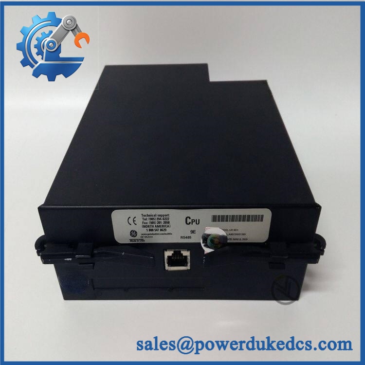
GE UR9AH
Application Scenarios & Field Realities
- On legacy feeder protection panels, the can remain part of the original control architecture where an older F35 configuration is still in service. Replacing only the failed CPU can avoid unnecessary disturbance to field CT circuits and existing relay wiring, provided the complete hardware generation remains matched.
- For generator protection systems using older G60 hardware, the CPU module provides the logic-processing layer that works with the relay’s measurement and I/O modules. The replacement task should therefore start with the installed CPU and CT/VT order codes, not merely the relay front-panel model.
- During a forced outage on a legacy UR installation, a same-generation spare can be valuable because the engineer is restoring an established architecture rather than introducing a new hardware family. Check the configuration file first. Then compare the replacement module’s identification and hardware generation.
- Where a site is planning phased migration, the is also relevant as a reference point for deciding whether to maintain the existing architecture or move toward a later CPU generation. Published service information identifies the 9E CPU as a functional modernization path, but a CPU-only swap is not automatically sufficient because CT/VT hardware generation must also be considered.
Migration, Compatibility & Installation Traps
Replacement Matrix
| Replacement Case | Classification | Engineering Requirement |
|---|---|---|
| replacing the same | Drop-in Replacement | Verify exact part number, hardware generation, relay settings, connectors, and existing CT/VT module |
| replacing another legacy 9A/9C/9D CPU variant | Software Compatible | Confirm the relay model, communications configuration, firmware, and original order-code options before commissioning |
| migrated to a later-generation CPU architecture | Hardware Modification Required | Evaluate CPU/CT-VT generation, firmware, configuration, and any associated module changes |
The major compatibility trap is hardware-generation matching. Technical references identify the as an older CPU generation and state that it must be matched with older CT/VT modules such as the 8A, 8B, 8C, or 8D families. Mixing an older CPU with later CT/VT hardware can produce DSP ERROR or HARDWARE MISMATCH conditions during initialization.
Field Traps — Watch Out
CPU/CT-VT generation mismatch: A module can be physically installed and still fail system initialization. Before removing the existing CPU, record the installed CT/VT order code and CPU hardware information. Do not assume slot compatibility means system compatibility.
Configuration loss: Keep a verified copy of the existing UR settings before replacement. After installation, verify relay identification, protection settings, logic configuration, communications parameters, and event/status reporting before returning the protection scheme to service.
RS485 wiring: The uses serial interfaces. Check the existing Modbus RTU or DNP wiring, device address, baud rate, parity, and termination arrangement before reconnecting the communication network. A CPU replacement should not be used as an opportunity to alter a functioning serial topology without a documented reason.
Quality Assurance SOP
Each supplied from surplus inventory should pass a controlled pre-shipment inspection rather than a label-only check:
- OEM anti-counterfeit visual inspection — compare GE identification labels, model marking, serial information where present, housing construction, connector condition, board appearance, and evidence of unauthorized repair or modification.
- Mechanical inspection — examine the enclosure, mounting surfaces, connector pins, retention hardware, and PCB for impact, corrosion, contamination, or bent contacts.
- Power-on self-test (POST) — install the CPU in an appropriate UR test configuration and observe the relay startup sequence and available ERR/RUN diagnostic indications.
- CPU recognition check — confirm that the host UR system identifies the installed CPU and that no immediate hardware-generation or initialization fault appears.
- Communication handshake verification — establish the applicable serial communication link and verify basic communication through the supported / Modbus RTU or DNP interface.
- Module coordination check — verify CPU interaction with the installed CT/VT and I/O architecture under the controlled test configuration.
- Configuration verification — compare the tested hardware identity with the intended relay configuration and document any firmware or hardware-generation limitations.
- Final inspection — photograph the exact unit, record the model and serial information where available, apply ESD protection, and package the CPU for industrial shipment.
For an older , the QA objective is not merely “powers on.” The meaningful acceptance test is whether the CPU initializes correctly with the intended UR hardware generation and communicates with the expected relay architecture without producing a DSP ERROR or HARDWARE MISMATCH condition.











 Start Chat


