

Description
- Brand: GE
- Full Model Number: VG5SK8I052311 PM0N2000
- System/Series Family: GE Industrial Control / Legacy VME-Based Hardware
- Core Function: Industrial control module identified in available references as a digital-input/control module
- Top 3 Hardcore Specs: VG5SK8I052311 identifier | PM0N2000 designation | Industrial control application
- Module Type: Control / I/O module
- Interface: Exact I/O and electrical interface to be verified against the installed hardware revision
- Architecture: Legacy industrial control hardware
- Stock Status: New Surplus — exact condition, revision, and packaging to be verified before shipment
Technical Product Introduction
The GE VG5SK8I052311 PM0N2000 is a legacy GE industrial control module that appears in current spare-parts references under the combined identifiers VG5SK8I052311 and PM0N2000. Available technical listings variously classify the unit as a digital-input module, industrial control module, or Ethernet-related I/O hardware, while other listings incorrectly associate unrelated specifications with the same number. Because those descriptions conflict, the safest engineering identification is the complete physical part number rather than an assumed generic function.
For procurement and replacement work, the VG5SK8I052311 marking should be treated as the primary identification reference, with PM0N2000 retained as the associated designation. Publicly available sources do not provide a sufficiently consistent OEM specification for confirmed channel count, voltage range, communication protocol, dimensions, or power consumption. Those values should therefore be verified from the unit nameplate, GE documentation, or the customer’s installed-system records before a like-for-like substitution is approved. This is one of those legacy-part situations where a photograph of the connector side can prevent an expensive ordering error.
Application Scenarios & Field Realities
- Within legacy industrial control cabinets, the module may form part of a larger control or I/O architecture. Before replacement, document every cable and connector position rather than relying on the model number alone.
- For digital signal acquisition, available references identify the part as a digital-input module, but they do not consistently publish a confirmed channel count or input voltage specification. The installed wiring should therefore be used to establish the actual field interface before commissioning.
- Where older GE control equipment remains in service, retaining the exact VG5SK8I052311 hardware can avoid an unnecessary redesign of the surrounding rack or cabinet. Hardware revision and connector geometry still need to match.
- During planned shutdown maintenance, record the original module’s label, board revision, connector arrangement, firmware or configuration information if applicable, and cabinet slot position. That evidence is more useful than a generic catalog description when dealing with an obsolete or poorly documented assembly.
Migration, Compatibility & Installation Traps
Replacement Matrix
| Replacement Condition | Assessment | Engineering Requirement |
|---|---|---|
| Same PM0N2000 hardware and matching revision | Drop-in Replacement Candidate | Verify physical interface, slot position, electrical ratings, and host-system recognition |
| Same base model with a different hardware revision | Software Compatible — verification required | Check host-system compatibility and configuration before returning the cabinet to service |
| Different GE module with similar stated function | Compatibility Review Required | Compare connector pinout, I/O characteristics, addressing, and mechanical dimensions |
| Different module family or interface architecture | Hardware Modification Required | Re-engineer wiring, mounting, configuration, and commissioning as applicable |
Field Traps — Watch Out
Do not order from the generic description alone. Public listings for this exact number contain materially inconsistent classifications, including digital I/O, Ethernet I/O, transistor, and other descriptions. The complete marking and physical configuration should take precedence.
Connector pinout must be verified before energization. Do not assume that another GE module with a similar housing or function uses the same terminal assignment. Obtain the original wiring diagram or compare the replacement against the removed unit.
Configuration backup comes first. If the module participates in a programmable control architecture, save the existing application/configuration data before replacement. A physically correct spare can still require configuration restoration or system-level validation.
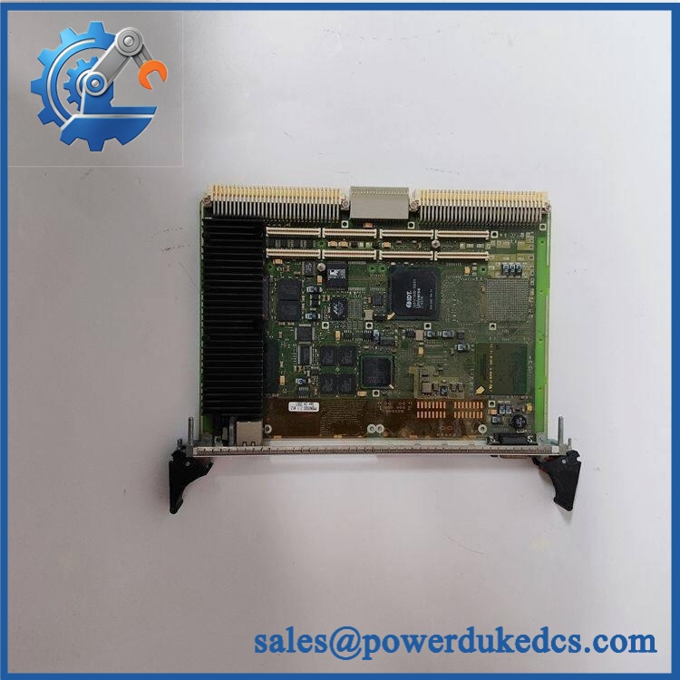
GE VG5SK8I052311 PM0N2000
Quality Assurance SOP
Before shipment, each available unit should pass a documented inspection sequence:
- OEM anti-counterfeit visual inspection — Verify GE markings, complete identification, PM0N2000 designation, labels, board markings, and manufacturing identifiers.
- Physical configuration inspection — Compare the replacement against reference photographs or the customer’s existing unit, including housing, connectors, mounting points, labels, and board layout.
- PCB inspection — Check for corrosion, contamination, cracked components, damaged solder joints, overheating marks, unauthorized modifications, and mechanical stress.
- Connector inspection — Examine every connector for bent pins, oxidation, damaged locking features, contamination, and loose contacts.
- Electrical specification verification — Confirm the actual voltage, current, I/O, and communication characteristics from the unit documentation or customer-supplied technical records. Do not substitute unverified catalog specifications.
- Controlled power-up test — Where a compatible GE test environment is available, power the module under controlled conditions and check for abnormal indicators, diagnostic faults, or excessive current draw.
- I/O verification — If the unit is confirmed as a digital-input/control module for the customer’s system, test each applicable channel using the correct signal level and verify that the host system recognizes the expected state.
- Communication or host-recognition verification — Where applicable, verify that the host controller recognizes the module and that no configuration or hardware fault is reported.
- Thermal observation — Monitor the module during the controlled test for abnormal heating or unstable operation.
- Final identification check — Match the physical unit, nameplate, model number, revision, and purchase order before packing.
- ESD-safe packaging inspection — Protect the module in suitable ESD packaging with mechanical protection around connectors and exposed PCB areas.
- Shipment release — Any discrepancy involving the identification, revision, connector arrangement, or test result stops shipment until resolved.











 Start Chat


