

Description
- Brand: GE Fanuc / VMIC
- Full Model Number: VMIVME-2540
- System/Series Family: VMIC VMEbus Intelligent Counter/Controller Series
- Core Function: High-speed digital counting measurement and programmable waveform generation over the VMEbus
- Top 3 Hardcore Specs: 24 input/output interfaces; 15 MHz 68HC000 onboard CPU; A32/A24/D32/D16/D8 VME slave interface with 64 KB memory window
- Stock Status: New Surplus — exact unit condition and availability to be verified
The VMIVME-2540 is a VMEbus Intelligent Counter/Controller (ICC) designed for precision digital measurement and function generation. The platform supports configurable 4-, 8-, 16-, or 24-interface versions, with RS-422 differential signaling and support for single-ended TTL inputs.
Technical Product Introduction
A conventional digital I/O card is not enough when the application needs to measure frequency, pulse width, shaft position, or event timing without forcing the VME host CPU to poll every transition. The GE VMIVME-2540 moves those time-critical measurement and generation functions into an intelligent VMEbus slave module. Its architecture combines a 15 MHz 68HC000 processor, dedicated counter circuitry, and a memory-mapped VME interface. The module supports up to 24 control and measurement interfaces, including clocks, gates, and outputs.
The useful performance figures are unusually specific. Event counting reaches 4 giga events; frequency measurement extends from 1.16 × 10⁻³ Hz to 2.5 MHz; period or pulse-width measurement can cover 400 ns to 8.5899 × 10⁶ s in the 32-bit floating-point mode. Square-wave and pulse-train generation reaches 2.5 MHz, while quadrature position measurement supports sine/cosine signals up to 1 MHz with 32-bit counters. The VME interface supports A32/A24/D32/D16/D8 transfers through a 64 KB VMEbus memory window.
Application Scenarios & Field Realities
- Rotating machinery measurement: For shafts, motors, turbines, or test rigs where speed and angular position matter, the VMIVME-2540 can perform event counting, frequency measurement, and quadrature position measurement directly at the I/O layer. That reduces dependence on software polling from the host processor.
- Automotive and dynamometer testing: Brake, transmission, tachometer, and rotational test systems are specifically listed among the module’s applications. Pulse-width and frequency measurements from fast-changing signals are handled by the counter hardware rather than treated as ordinary slow digital states.
- Robotics and motion equipment: In position-control applications, the quadrature measurement and programmable output functions can be used for feedback acquisition and pulse generation. The module supports quadrature control outputs with a step rate up to 1.25 MHz.
- Machine tools and industrial positioning: When an old VME controller must measure encoder pulses, generate pulse trains, or detect events with tight timing, the 2540 provides dedicated hardware for those functions. —The exact interface count must be matched to the factory configuration of the unit being replaced.
Migration, Compatibility & Installation Traps
Replacement Matrix
| Replacement Type | Assessment |
|---|---|
| Drop-in Replacement | Yes, for an existing VMIVME-2540 installation with the same interface option and VME hardware configuration |
| Software Compatible | Yes at the VMEbus device level, subject to existing register mapping, firmware, and application software |
| Hardware Modification Required | Normally no for an exact same-model replacement; connector and interface configuration must still be verified |
The VMIVME-2540 was offered with 4, 8, 16, or 24 interfaces, so the base model number alone does not necessarily establish the exact factory configuration. The ordering structure uses an interface-option code to select the channel count. This is important when replacing an installed board: compare the complete part marking and ordering code rather than assuming every has the full 24-interface configuration.
Field Traps — Watch Out
Interface-count mismatch: A replacement board with fewer configured interfaces can appear functional while leaving part of the machine’s original signal set unavailable. Verify the exact factory option before installation.
RS-422 versus TTL wiring: The module supports RS-422 differential interfaces and single-ended TTL inputs. Do not move field wiring simply because the connector appears identical; confirm the electrical interface used by the existing equipment.
VME address configuration: The board operates as a VMEbus slave with configurable memory-mapped access. Confirm the existing address arrangement and host software assumptions before commissioning a replacement. A bus-visible board is not necessarily a correctly configured board.
Counter reset behavior: Event counters and timing functions should be checked after startup. A replacement may initialize differently from the previous unit depending on stored configuration and application firmware, so verify counter presets, timing parameters, interrupt settings, and output modes before returning the machine to service.
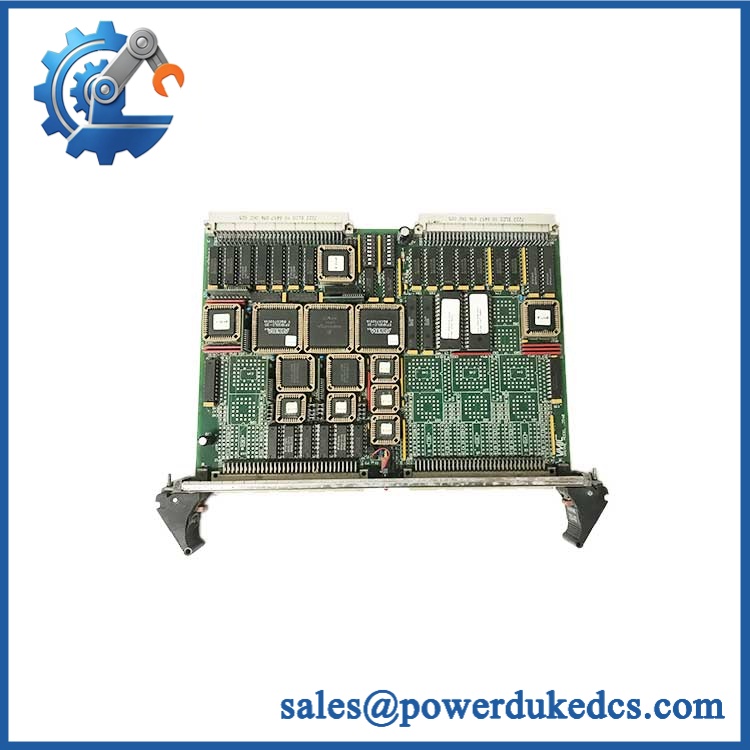
GE VMIVME-2540
Quality Assurance SOP
For surplus inventory, testing should focus on the onboard processor, VMEbus interface, timing channels, and the exact factory interface option.
- OEM anti-counterfeit visual inspection: Verify GE Fanuc / VMIC markings, part identification, board revision, connector arrangement, PCB markings, and visible option codes.
- Mechanical inspection: Examine the PCB, front panel, connectors, card guides, solder joints, and component areas for cracks, corrosion, contamination, bent contacts, or evidence of unauthorized rework.
- Configuration verification: Record the interface-option code and determine whether the unit is configured for 4, 8, 16, or 24 interfaces.
- Power-on self-test (POST): Install the board in a compatible VME test chassis and monitor host initialization, board recognition, bus errors, and abnormal processor status during startup.
- VMEbus access test: Verify A32/A24 addressing and D32/D16/D8 data transactions through the expected VMEbus memory window.
- CPU execution test: Confirm normal operation of the onboard 15 MHz 68HC000 CPU and associated counter-control firmware functions.
- Event counting verification: Apply controlled pulse inputs and verify event accumulation across representative counter channels, including rollover and reset behavior.
- Frequency measurement verification: Apply known-frequency signals across the supported range and compare reported values with the calibrated test source.
- Period and pulse-width verification: Use controlled timing pulses to verify measurement accuracy in the applicable 16-bit and 32-bit operating modes.
- Waveform generation test: Command programmed pulse trains or square-wave outputs and verify frequency, timing, and output-state behavior up to the supported limits.
- Quadrature verification: Where the installed configuration supports the function, apply a known quadrature signal and verify position-count direction, count integrity, and programmed control output behavior.
- Communication handshake verification: Confirm stable data exchange between the VME host and the through the documented memory-mapped interface, with no recurring bus timeout or access fault.
- Extended operating check: Run representative counter and waveform-generation functions for the defined QC interval while monitoring for processor resets, counter corruption, unstable outputs, or intermittent VMEbus errors.
- Final traceability check: Record model number, complete option code, hardware revision, serial or identification information where available, test date, functional results, and shipment condition.
The defining characteristics of the are its intelligent counter architecture, up to 24 configurable interfaces, 15 MHz 68HC000 onboard CPU, RS-422/TTL signal support, and VMEbus slave interface supporting A32/A24/D32/D16/D8 transfers. Its measurement functions include event counting, frequency, period, pulse width, and quadrature position, while its generation functions include pulse trains, square waves, timers, and quadrature control.











 Start Chat


