

Description
- Brand: GE
- Full Model Number: VMIVME-5565-010000
- Alternate Part Number: 332-015565-010000P
- System/Series Family: GE VMIC / VMIVME Reflective Memory
- Core Function: VMEbus reflective-memory interface for deterministic data sharing between distributed computer nodes
- Top 3 Hardcore Specs: 1 Gbaud serial link | VMEbus interface | Reflective-memory architecture
- Data Transfer: Up to 174 MB/s sustained system-level transfer under specified conditions
- Memory: 128 MB dual-ported reflective memory
- Node Architecture: Up to 256 nodes in a reflective-memory network
- Fiber Interface: Duplex fiber-optic connection
- Stock Status: New Surplus — exact hardware revision and packaging condition to be verified before shipment
Technical Product Introduction
When several industrial computers need the same process data without repeatedly polling a central controller, reflective memory provides a different architecture: data written by one node is automatically propagated across the network to the corresponding memory space of other nodes. The GE VMIVME-5565-010000 is a VMIC reflective-memory interface board for VMEbus systems, identified by the alternate part number 332-015565-010000P. The board uses a high-speed fiber-optic network to distribute shared data between VME-based computing nodes.
The published architecture provides 128 MB of dual-ported reflective memory and supports data transmission at up to 1 Gbaud, with system-level sustained transfer rates reported at up to approximately 174 MB/s under specified conditions. The architecture can support networks of up to 256 nodes, depending on system configuration. These characteristics make the board useful in distributed simulation, industrial control, data acquisition, and other VME systems where predictable shared-memory behavior is more important than conventional network messaging. Exact performance depends on topology, node configuration, VME access patterns, and application software.
Application Scenarios & Field Realities
- In distributed industrial control racks, one VME computer can write process data into reflective memory while other nodes access the replicated data without repeatedly requesting it from the source processor. This can reduce software-level polling overhead.
- For high-rate data acquisition systems, the 128 MB memory space provides a shared data region between VME nodes. The actual usable data structure should be defined by the application software and synchronized across every participating node.
- During simulation and test-system operation, reflective memory can distribute common datasets among multiple computing nodes with predictable propagation behavior. The fiber network still needs to be engineered for the required node count and cable routing.
- When maintaining legacy VMIC installations, the complete part number matters. VMIVME-5565-010000 and 332-015565-010000P should be cross-checked against the physical label, hardware revision, fiber interface, memory configuration, and installed driver environment before approving a replacement.
Migration, Compatibility & Installation Traps
Replacement Matrix
| Replacement Condition | Assessment | Engineering Requirement |
|---|---|---|
| Same VMIVME-5565-010000 revision and matching configuration | Drop-in Replacement Candidate | Verify VME slot, fiber interface, memory configuration, firmware, and driver support |
| Same 5565 family with different hardware revision | Software Compatible — verification required | Confirm driver/BSP support and validate reflective-memory initialization |
| Different reflective-memory VME module | Compatibility Review Required | Compare memory size, network protocol, fiber interface, VME resources, and software API |
| Non-reflective-memory VME interface | Hardware Modification Required | Requires changes to network architecture, application software, and potentially data-sharing logic |
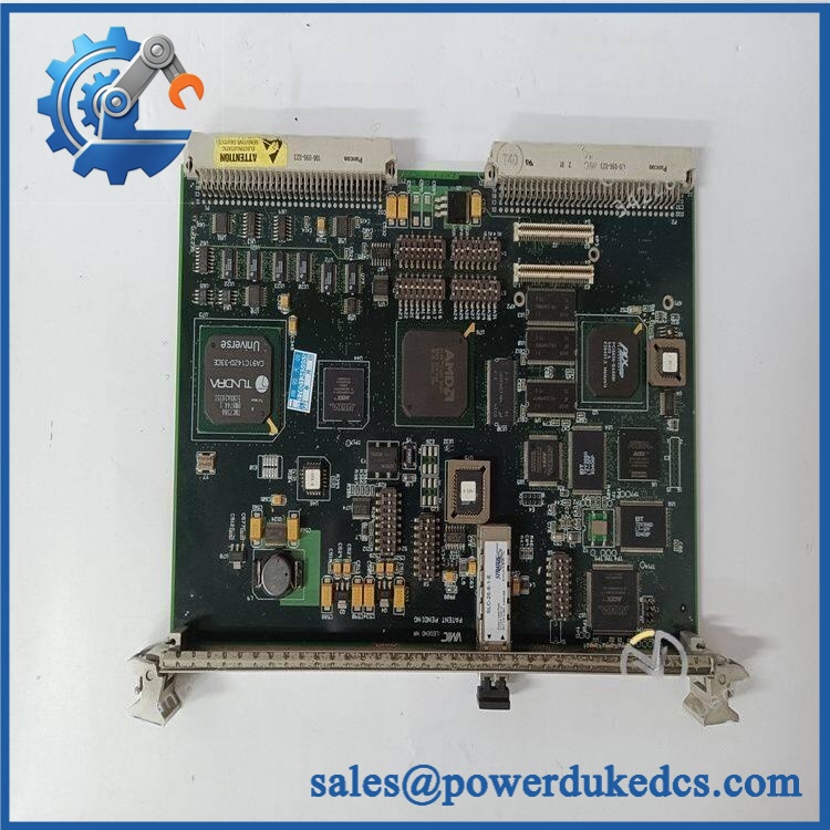
GE VMIVME-5565-010000
Field Traps — Watch Out
Fiber topology must be preserved. Reflective-memory systems depend on the network topology and node configuration. A replacement board that powers up correctly can still fail to join the existing memory network if its node address, termination arrangement, or fiber connection is incorrect.
Driver compatibility matters as much as the board. The host application normally interacts with reflective memory through device drivers or a board-specific software interface. Before replacement, record the host operating system, driver version, application configuration, and memory-map settings.
Do not confuse serial link rate with application throughput. The 1 Gbaud network specification does not mean every application will achieve 1 Gbaud of usable payload throughput. VME transaction patterns, packet overhead, memory access, and network topology affect practical performance.
Fiber handling is unforgiving. Keep optical connectors capped when disconnected. Inspect and clean fiber ends using the approved procedure before reconnecting; contamination can produce intermittent link faults that resemble a failed board.
Quality Assurance SOP
Before shipment, each available GE VMIVME-5565-010000 / 332-015565-010000P unit should pass a documented inspection sequence:
- OEM anti-counterfeit visual inspection — Verify GE/VMIC markings, VMIVME-5565-010000 identification, alternate part number, labels, PCB identifiers, and hardware revision.
- Memory configuration verification — Confirm the expected reflective-memory architecture and inspect the board for the documented memory configuration.
- VME connector inspection — Examine the VME backplane connector for bent, recessed, oxidized, contaminated, or mechanically damaged contacts.
- Fiber interface inspection — Check optical connectors, retaining hardware, protective caps, and surrounding components for contamination or physical damage.
- PCB inspection — Examine the board for corrosion, cracked components, damaged solder joints, overheating marks, missing components, or unauthorized modifications.
- Controlled power-up test — Install the board in a compatible VME test chassis and verify normal power consumption, startup behavior, and diagnostic indicators.
- VMEbus recognition verification — Confirm that the host system identifies the board and that no abnormal VMEbus errors occur during controlled access.
- Reflective-memory initialization test — Establish a controlled test network with a compatible second node and verify successful initialization and node recognition.
- Memory propagation test — Write controlled test data from one node and verify that the corresponding memory contents appear correctly on the receiving node.
- Link integrity verification — Test the fiber connection for stable network operation and check for link or communication errors during extended operation.
- Throughput observation — Where the test platform permits, perform a controlled data-transfer test and record observed performance rather than claiming the theoretical maximum.
- Extended operation test — Monitor the board for abnormal heating, resets, memory errors, network faults, or intermittent communication.
- Final identification check — Match the tested board’s model, alternate part number, hardware revision, and physical condition against the purchase order.
- ESD and optical-safe packaging — Protect the PCB against ESD and protect all fiber interfaces with suitable caps and mechanical packaging.
- Shipment release — Any discrepancy involving the identification, memory configuration, fiber interface, or test result stops shipment until resolved.











 Start Chat


