

Description
- Brand: GE Fanuc / VMIC
- Full Model Number: VMIVME-7452
- System/Series Family: VMIC VMEbus Embedded Computer Systems
- Core Function: Single-slot VMEbus storage module supporting hard disk, floppy disk, and optional Flash storage
- Top 3 Hardcore Specs: 6U single-slot VMEbus; 3.5-inch 1.44 MB floppy drive; up to 18.0 GB hard-disk storage
- Stock Status: New Surplus — drive capacity and exact hardware configuration to be confirmed
The VMIVME-7452 is a 6U single-slot VMEbus floppy/hard-disk module designed for GE Fanuc/VMIC embedded VME processors. It is a passive board that connects to the VMEbus P2 user-defined pins, power, and ground; the storage controllers reside on the compatible single-board computer.
Module 3: Technical Product Introduction
When an older VME computer loses its boot drive or removable-media interface, replacing the SBC is often unnecessary. The GE Fanuc VMIVME-7452 provides dedicated storage hardware within a standard 6U single-slot VMEbus form factor, supporting a hard disk and 3.5-inch 1.44 MB floppy drive, with Flash storage available as an option. GE documentation describes the module as a passive board intended for VMIC VMEbus-compatible PC/AT single-board computers with onboard IDE and floppy controllers.
The published specification lists dimensions of approximately 233.4 × 160 × 20.3 mm, with a 34-pin floppy connector and 40-pin IDE connector. The hard-drive configuration was specified for up to 18.0 GB, while the Flash option provides a typical burst transfer rate of 4.0 MB/s to Flash and 6.0 MB/s from Flash. The module operates from +5 VDC, with typical current below 1 A and up to 2.5 A during hard-drive spin-up.
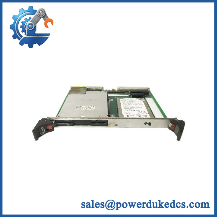
GE VMIVME-7452
Module 4: Application Scenarios & Field Realities
- Inside legacy VME computer cabinets, the VMIVME-7452 provides local storage for compatible VMIC/GE Fanuc SBCs without consuming a second processor position. The physical placement is important because the IDE/floppy connection is made through the VME P2 user-defined pins.
- For systems retaining floppy-based service procedures, the integrated 3.5-inch 1.44 MB floppy interface can remain part of the maintenance workflow. This is particularly relevant when application software or machine configuration files are stored on legacy removable media.
- When replacing a failed hard drive, verify the actual drive capacity and interface before ordering the complete VMIVME-7452. The module itself is a storage carrier/interface assembly; the exact installed drive configuration can vary.
- For Flash-equipped installations, check the operating system’s write behavior before using Flash as a hard-disk substitute. GE specifically cautioned against operating systems that perform excessive writes because of the Flash device’s finite write/erase cycle life.
Module 5: Migration, Compatibility & Installation Traps
Replacement Matrix
| Replacement Type | VMIVME-7452 Assessment | Engineering Requirement |
|---|---|---|
| Drop-in Replacement | Yes, for a matching VMIC/GE VME installation | Verify SBC compatibility, drive configuration, cable assembly, and VME slot arrangement |
| Software Compatible | Host-dependent | The SBC’s operating system and IDE/floppy drivers must support the installed storage device |
| Hardware Modification Required | Potentially | Required when the existing SBC, P2 pinout, cable arrangement, or storage architecture differs |
Field Trap 1 — The is not a standalone disk controller:
This is a passive VME board. The compatible SBC supplies the IDE and floppy controller functions, while the provides the physical storage interfaces. Do not expect the module to operate as an independent VME mass-storage controller.
Field Trap 2 — Cable selection depends on rack layout:
For a typical single-slot SBC positioned adjacent to the , GE specifies the VMXC-3 cable assembly. For a double-slot processor or a non-adjacent installation, the 14-inch VMXC-H cable is recommended.
Installation note: Remove VME rack power before installing or removing the module. Verify the P2 connection, IDE/floppy cable orientation, drive mounting, and available +5 VDC capacity before startup. Hard-drive spin-up can raise the module’s current demand to approximately 2.5 A maximum according to the published specification.
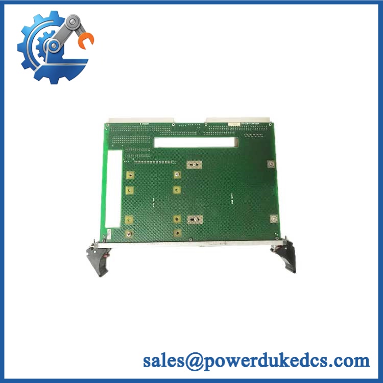
GE VMIVME-7452
Module 6: Quality Assurance SOP
- OEM identification inspection — Verify the GE Fanuc/VMIC marking, serial information, revision labels, and any installed drive identification.
- Physical board inspection — Examine the 6U VME board, P1/P2 connectors, drive mounting points, IDE connector, floppy connector, cable interfaces, and PCB surfaces for damage or corrosion.
- OEM anti-counterfeit visual inspection — Compare GE Fanuc/VMIC labeling, board construction, connector placement, slot geometry, and component markings against authenticated reference hardware.
- Storage-device verification — Identify whether the unit contains a hard disk, floppy drive, Flash option, or a combination. Record the installed drive manufacturer, model, capacity, and interface.
- Power-path inspection — Check the VME power connections and verify that the test rack can supply the required +5 VDC current. Pay particular attention to hard-drive startup demand.
- Power-on self-test (POST) — Install the with a compatible SBC and verify that the host system powers up without abnormal current draw or hardware faults.
- IDE interface verification — Confirm that the host SBC detects the installed hard disk and can perform controlled read/write operations.
- Floppy interface verification — Where equipped, test the 3.5-inch 1.44 MB floppy drive for media detection, read, write, and formatting functions.
- Flash verification — Where a Flash option is installed, perform controlled read/write testing and check the device’s response after reset. Avoid unnecessary repeated write cycles during testing.
- Cable and P2 verification — Confirm the correct cable assembly and connector orientation for the specific SBC/rack arrangement. The uses P2 user-defined connections rather than acting as a conventional VMEbus data-processing module.
- Final traceability record — Photograph the complete module label and installed storage devices, record capacity and revision information, document test results, and package the module with ESD and mechanical protection.
For , the critical replacement parameters are the 6U single-slot VMEbus format, compatible VMIC SBC, P2 IDE/floppy connection, installed storage configuration, and cable arrangement. The module is specifically documented as a floppy/hard-disk storage option for VMIC VME processors, rather than a general-purpose VME I/O card.











 Start Chat


