

Description
- Brand — GE
- Full Model Number — WEA13-13 / 2508-21001
- System/Series Family — WESDAC / WES13-3
- Core Function — Isolated analog output module for industrial control and substation automation applications
- Top 3 Hardcore Specs — Isolated analog output; WES13-3-associated module; GE WESDAC control architecture
- Stock Status — New Surplus / availability subject to physical inventory confirmation
Technical Product Introduction
A failed analog-output module can stop a control loop even when the main controller remains healthy. GE WEA13-13 2508-21001 is identified in available product records as an isolated analog output module associated with the WESDAC/WES13-3 family. Its role is to provide conditioned analog signals between the control system and downstream field devices. Exact channel count, output ranges, terminal assignments, and electrical limits should be matched against the installed WESDAC hardware documentation before replacement.
For maintenance teams, the important point is configuration fidelity rather than simply matching the model number. WEA13-13 and 2508-21001 should be checked together because the latter is reported as the factory part number. Available technical listings conflict on several detailed specifications, including channel count, operating voltage, and interface architecture, so those values should not be treated as OEM-confirmed without the applicable GE documentation or an existing-unit inspection. That distinction matters during emergency replacement—especially when an output card drives a control valve, actuator, or other process device.
Application Scenarios & Field Realities
- In substation automation cabinets, the module can be used where isolated analog signals must be passed from the control architecture toward field equipment. Check the existing terminal arrangement before removing the failed card; similar-looking WESDAC modules are not automatically interchangeable.
- Where an analog control loop is tied to a critical actuator, replacement should start with the channel wiring schedule, not the physical dimensions. Confirm the signal type and scaling in the active configuration before restoring the loop.
- For legacy GE control installations, WEA13-13 2508-21001 can be relevant as a maintenance spare when the original system remains operational but replacement inventory has become difficult to source. The WES13-3 association is specifically reflected in current product listings.
- During emergency cabinet repair, photograph terminal positions, module identification labels, jumper settings, and status indicators before disassembly. A five-minute record can prevent an incorrect signal assignment after installation.
Migration, Compatibility & Installation Traps
Replacement Matrix
| Replacement condition | Assessment | Engineering requirement |
|---|---|---|
| Same WEA13-13 / 2508-21001 | Drop-in Replacement | Verify hardware revision, terminal arrangement, and system configuration first |
| Same WEA13-13 with different revision | Software/Configuration Verification | Compare firmware or configuration requirements before energizing |
| Different WESDAC module | Hardware Modification Required | Do not assume terminal or electrical compatibility from physical similarity |
Field Trap 1 — Signal-range mismatch:
Do not transfer field wiring until the installed module’s actual output range has been confirmed. Current online listings disagree about detailed electrical specifications, so values such as output range, channel count, and supply requirements should be verified from the module label and applicable GE documentation rather than copied from an unverified listing.
Field Trap 2 — Configuration loss:
Record the existing channel configuration before replacement. After installation, verify every affected output against the control-system configuration and field loop documentation. Do not assume that a physically identical replacement retains the original configuration.
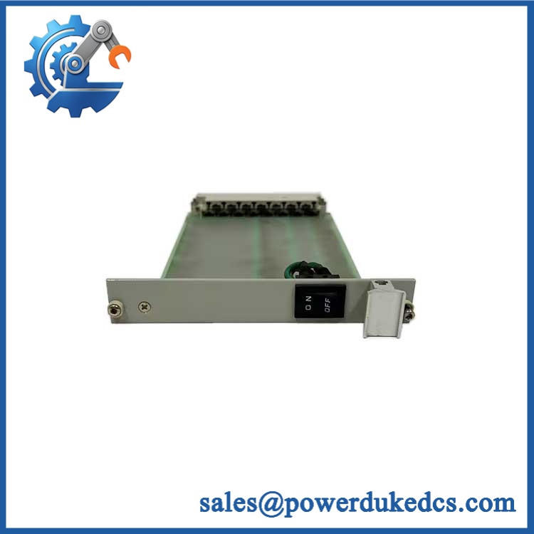
GE WEA13-13 2508-21001
Quality Assurance SOP
For New Surplus 2508-21001 inventory, the pre-shipment process should include:
- OEM anti-counterfeit visual inspection — compare GE identification labels, part number 2508-21001, model marking , board construction, connectors, and manufacturing markings against known OEM characteristics.
- Physical-condition inspection — inspect PCB surfaces, terminal interfaces, connectors, mounting hardware, labels, and evidence of corrosion, impact, oxidation, or unauthorized repair.
- Part-number verification — confirm that the physical unit matches both and 2508-21001 before packing.
- Power-on self-test (POST) — where the available test fixture supports the module, energize the unit and check the expected diagnostic/status indicators for abnormal ERR, FAIL, or RUN conditions.
- I/O verification — test supported analog output channels against the applicable GE test procedure or known-good reference equipment.
- Communication handshake verification — where the installed test architecture provides a communication interface, verify that the module exchanges expected status or data with the associated control hardware.
- Configuration record — photograph the nameplate, revision markings, terminal side, and test status before shipment.
- ESD-controlled packing — place the tested module in ESD-safe packaging with adequate mechanical protection for international transportation.
Technical note: detailed electrical limits and channel specifications should be treated as to be verified against the applicable GE documentation because publicly available secondary listings contain conflicting specifications for this exact part number.











 Start Chat


