

Description
- Brand: GE
- Full Model Number: WES13-3 5167-0001-0210
- System/Series Family: GE WES13-3 Excitation System
- One-Sentence Core Function: Digital excitation controller / automatic voltage regulator for synchronous-generator excitation systems
- Top 3 Hardcore Specs: Generator PT/CT feedback; field-current feedback; thyristor firing-pulse output
- Control Modes: Automatic voltage regulation; manual field-current control; reactive-power / power-factor control subject to system configuration
- Stock Status: New Surplus / Fully Tested Refurbished subject to actual inventory inspection
Module 3: Commercial-Technical Deep Dive
A generator excitation controller can become the single point preventing a unit from returning to service after an excitation-system failure. The GE WES13-3 5167-0001-0210 is identified in current industrial references as a digital excitation-system controller / automatic voltage regulator (AVR) for synchronous generators. Its control inputs include generator terminal-voltage feedback from PT circuits, stator-current feedback from CT circuits, and field-current feedback, while its output interfaces with the thyristor power bridge that regulates field excitation.
The commercial value is in restoring an existing excitation architecture without replacing the complete power bridge and associated cabinet. The WES13-3 reference describes automatic voltage regulation together with manual field-current control and reactive-power or power-factor operating modes, depending on the installed system configuration. The same reference identifies a 125 VDC nominal logic supply and an RS-485 serial interface for service or supervisory communications. These specifications should be treated as configuration references rather than universal ratings for every WES13 installation; the plant wiring diagram, controller nameplate, firmware record, and excitation-system drawings remain the final authority.
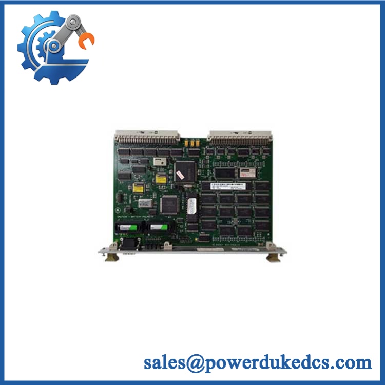
GE WES13-3 5167-0001-0210
Module 4: Compatibility & Installation Traps
Migration/Compatibility
- Replacement status: GE WES13-3 Digital Excitation Controller / AVR
- Logic rewrite: Configuration dependent. A true like-for-like replacement can preserve the existing excitation application, but controller configuration and operating parameters must be verified before commissioning.
- Firmware update: Configuration dependent. Record the installed firmware and parameter set before replacing the controller.
- Drop-in status: Not automatically guaranteed. The complete 5167-0001-0210 identifier, chassis/backplane, I/O configuration, firing-pulse interface, feedback circuits, and firmware environment should match.
- Input feedback: Generator PT voltage, stator CT current, and field-current feedback are identified for the -3 reference.
- Power: A current industrial reference lists 125 VDC nominal logic power fe 5167-0001-0210 configuration.
⚠️ Field Traps (Watch Out)
- PT/CT wiring: Never assume the feedback wiring matches another variant. Incorrect phase assignment, CT polarity, or PT scaling can produce incorrect voltage regulation.
- Firing-pulse interface: The controller interfaces with a thyristor power bridge. Verify the existing gate/firing circuit before installing a replacement; a controller with a different interface configuration should not be treated as equivalent.
- Parameter mismatch: Correct hardware with incorrect voltage setpoints, current limits, or excitation parameters can appear healthy while producing unsafe regulation behavior.
- Station-battery supply: Verify the actual control-power voltage and polarity before energizing the replacement. Do not apply 125 VDC solely because it appears in a secondary specification; confirm the installed cabinet documentation.
- Excitation safety: Isolate the generator excitation circuit and follow the site’s electrical safety procedure before disconnecting PT, CT, field-current, or firing-pulse wiring.
Module 5: Quality Assurance SOP
Before shipment, the E 5167-0001-0210 should undergo an excitation-controller-specific QA sequence:
- OEM anti-counterfeit visual inspection — verify GE/ identification, complete 5167-0001-0210 marking, PCB labels, connectors, terminal layout, and enclosure condition.
- Configuration reconciliation — record the complete model and any revision or firmware markings visible on the controller.
- Mechanical inspection — inspect connectors, mounting hardware, PCB surfaces, cooling components, terminals, and backplane interfaces for damage or contamination.
- Power-input verification — confirm the required control supply from the plant documentation before applying controlled laboratory power.
- Power-on self-test (POST) — verify controller startup, processor initialization, status indications, and diagnostic behavior.
- PT/VT input simulation — apply controlled simulated generator-voltage signals and verify correct measurement and scaling.
- CT input simulation — apply representative current signals and confirm correct magnitude, phase relationship, and measurement response.
- Field-current feedback verification — simulate the field-current input and verify the controller’s measurement and diagnostic response.
- Regulation-loop simulation — use an approved excitation-system test fixture to evaluate automatic voltage-regulation response without connecting to a live generator.
- Manual/automatic transfer verification — where supported by the installed configuration, verify controlled transfer between operating modes.
- Firing-interface verification — using the correct test equipment, confirm expected firing-pulse output behavior to the compatible power-bridge interface.
- Serial communication handshake — verify the available RS-485/service interface against a controlled test environment where applicable.
- Final QC record — document part number, firmware identification, parameter set, simulated PT/CT/field-current values, output tests, photographs, and packaging condition.
For an excitation controller, a normal boot screen is not a functional acceptance test. Feedback scaling, regulation response, mode transfer, diagnostics, and firing-interface behavior are the meaningful checkpoints.
Module 6: CRO-Driven Buyer FAQ
1.E 5167-0001-0210 obsolete, and how do I verify an authentic replacement?
The is legacy excitation-system hardware, and current industrial references identify 5167-0001-0210 specificalla excitation controller. For procurement, verify the complete part number, PCB revision, firmware identification, connector arrangement, and the existing excitation-system configuration rather than ordering a generic controller.
2. Can I hot-swe ?
Do not assume hot-swap capability. The controller interfaces with generator PT/CT circuits, field-current feedback, and thyristor firing circuitry. Shut down and isolate the applicable excitation equipment, verify the absence of hazardous energy, and follow the site’s LOTO and generator-maintenance procedures before removal.
3. Will replacing the controller require reprogramming?
A like-for-like controller replacement may retain the existing application and parameter set, but do not commission it with factory-default settings. Preserve the existing configuration, firmware identification, voltage setpoints, field-current limits, protection parameters, and communication settings before removal.
4. What signals doe use?
The avae reference identifies generator terminal-voltage PT input, stator-current CT input, and field-current feedback, with firing-pulse output to the thyristor power bridge. It also lists automatic voltage regulation, manual field-current control, and reactive-power/power-factor operating modes subject to configuration.
5. What warranty and technical support are available?
Warranty duration should be stated according to the actual inventory condition, such as new surplus or tested refurbished. Technical support should cover exact part-number verification, excitation-system compatibility, firmware and parameter review, PT/CT scaling checks, firing-interface verification, and documented pre-shipment testing. Generator excitation commissioning, synchronization, protection coordination, and high-energy field work remain the responsibility of qualified electrical and excitation-system personnel.











 Start Chat


