

Description
- Brand: GE
- Full Model Number: WES5120 2340-21003
- System/Series Family: GE WES5120 / WESDAC Field Controller Architecture
- One-Sentence Core Function: WES5120 network and bus-interface hardware used for field-controller data expansion and industrial communications
- Top 3 Hardcore Specs: 2340-21003 hardware identifier; WES5120 platform; Ethernet/network communication function reported for this configuration
- Stock Status: New Surplus / Fully Tested Refurbished — exact hardware identity verified before shipment
Module 3: Commercial-Technical Deep Dive
A failed WES5120 communication module can interrupt remote-control data flow even when the field-controller processor and connected I/O remain operational. The GE WES5120 2340-21003 is repeatedly cataloged as a industrial automation module, with one current reference identifying it as a bus expansion component and another describing the same part number as a managed Gigabit Ethernet switch. That conflict is significant: the exact hardware function should be confirmed from the physical nameplate, board revision, connectors, and installed documentation before it is specified as a particular network device.
For a replacement order, the complete identifier is therefore more important than an assumed generic specification. One current listing reports a 24 VDC supply, Ethernet connectivity, -40 to +70°C operating range, and a compact 150 × 100 × 70 mm enclosure, while another source classifies the same part simply as a communication-control module. These figures should be treated as reported values rather than guaranteed engineering limits until the physical unit and applicable GE documentation are confirmed. The practical ROI remains clear: preserving the established communication architecture avoids unnecessary changes to field-controller wiring and upstream supervisory integration.
Module 4: Compatibility & Installation Traps
Migration/Compatibility
- Replacement status: Configuration-specific GE network/bus hardware.
- Exact identification: should be matched exactly against the installed unit.
- Functional classification: Public references conflict between bus-expansion hardware and managed Ethernet-switch functionality. Confirm the physical module before approving a drop-in replacement
- Firmware requirement: Do not assume a firmware update is necessary or permitted. Record the existing hardware revision, firmware, network parameters, and configuration before removal.
- Logic rewrite: Normally not required for an exact hardware replacement, but node addressing, port assignments, communication mapping, and supervisory configuration must be validated.
- Power requirement: One current reference reports 24 VDC input. Verify the actual nameplate and cabinet power circuit before energization.
⚠️ Field Traps (Watch Out)
- Function ambiguity: Do not purchase based solely on a description such as “Ethernet switch” or “bus expansion module.” The same 2340-21003 identifier is currently described differently by online sources. Use the physical label and connector arrangement as the final acceptance reference.
- Network configuration: Preserve IP address, subnet, gateway, node identity, VLAN settings where applicable, port mapping, and supervisory-system parameters before removing the original module.
- Connector mapping: Photograph every Ethernet, bus, power, and auxiliary connection. A similar enclosure does not guarantee identical port assignment.
- 24 VDC verification: If the installed unit uses the reported 24 VDC supply, confirm polarity and actual voltage before energization.
- ESD handling: Use grounded ESD protection when handling the electronics and protect communication connectors from contamination.
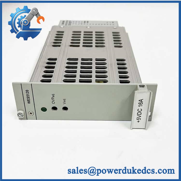
GE WES5120 2340-21003 WES5120
Module 5: Quality Assurance SOP
Our pre-shipment inspection for a GE 2340-21003 emphasizes exact identification and network functionality:
- OEM anti-counterfeit visual inspection — verify GE identification, marking, complete 2340-21003 identifier, revision information, serial labels, connectors, enclosure, and PCB markings.
- Part-number capture — photograph the front, rear, nameplate, connector field, and all secondary identification labels.
- Hardware-configuration verification — compare the physical module against customer photographs and installed-system documentation before testing.
- PCB and mechanical inspection — check connectors, mounting points, solder joints, communication components, contamination, corrosion, and evidence of overheating.
- Power-input verification — where the physical unit confirms the reported architecture, apply controlled 24 VDC power while monitoring startup behavior and current draw.
- Power-on self-test (POST) — verify startup diagnostics, status indicators, processor initialization, and abnormal fault conditions.
- Ethernet-interface test — where Ethernet hardware is fitted, establish a controlled link and verify link status, port activity, and stable data exchange.
- Bus-interface test — where the actual assembly provides a bus-expansion interface, verify the relevant bus path using a compatible test fixture.
- Network-configuration verification — confirm device identification, addressing, and expected port/interface behavior in an isolated test network.
- Communication handshake verification — connect to compatible /WESDAC test equipment and confirm stable controller-side communication.
- Extended communication observation — monitor link stability, repeated reconnects, packet errors, and abnormal temperature rise during controlled operation.
- Power-cycle test — perform controlled restart cycles and confirm that the module returns to the expected operational state without configuration loss.
- Configuration record — document hardware revision, firmware where accessible, network settings used for testing, measured supply voltage, communication results, and photographs.
- Final QC review — verify every recorded identifier against the customer’s exact requirement.
- ESD packaging — protect communication ports, terminals, and the electronics against ESD, dust, moisture, and mechanical impact.
Because available public sources give conflicting functional descriptions for 2340-21003, the QA procedure deliberately tests both the identified communication path and the physical hardware configuration rather than relying on a generic product title.
Module 6: CRO-Driven Buyer FAQ
1. Is GE 2340-21003 obsolete, and how do I verify authenticity?
The is a legacy GE field-controller and industrial communication platform. For 2340-21003, verify the complete part number, hardware revision, serial label, enclosure layout, connector arrangement, and installed system documentation. Current online references classify this exact number differently, so physical identification is especially important.
2. Is 2340-21003 a managed Ethernet switch or a bus expansion module?
Public references currently conflict. One source describes 2340-21003 as a bus-expansion component, while another calls it a managed Gigabit Ethernet switch.For a critical replacement, the installed unit’s nameplate, connector layout, and GE system documentation should determine the exact functional description.
3. What supply voltage does 2340-21003 use?
One current technical listing reports 24 VDC input. This should be treated as a reported specification until verified against the actual module label and cabinet schematic. Do not energize a replacement from an assumed supply range.
4. Can 2340-21003 be hot-swapped?
Do not assume live replacement is permitted. The unit participates in field-controller communications, and removal can interrupt remote-control or supervisory data. Isolate the relevant 24 VDC control supply, follow the GE/ maintenance procedure, and apply the site’s approved LOTO process before removal.
5. What configuration should be backed up before replacement?
At minimum, preserve the existing network address, subnet and gateway parameters, node identity, port mapping, supervisory-system configuration, and any -specific communication parameters. A replacement can pass POST while remaining offline because its communication configuration does not match the installed system.
6. What warranty and technical support should I expect?
Warranty duration should be stated on the quotation for the exact physical unit supplied. Technical support should cover part-number verification, hardware-revision matching, power-input confirmation, network configuration checks, communication testing, and documented pre-shipment QA results. It should not substitute for utility control engineering, SCADA commissioning, or site electrical-safety procedures.











 Start Chat


