

Description
- Brand: GE General Electric
- Full Model Number: WES5162
- System/Series Family: GE WES / WESDAC industrial control hardware
- Core Function: Rack/frame assembly for mounting and organizing GE control and I/O hardware
- Top 3 Hardcore Specs: 19-inch rack format; 7U height; approximately 483 × 305 × 356 mm reported dimensions
- Stock Status: New Surplus — physical configuration and condition to be verified before shipment
Technical Product Introduction
A failed rack frame can stop a replacement project just as effectively as a failed electronic card when the installed assembly depends on a specific mounting and interconnection arrangement. The GE WES5162 is identified by multiple current product references as a frame/rack assembly rather than a conventional CPU or I/O module. One published specification set reports a 19-inch format, 7U height, and approximately 483 × 305 × 356 mm overall dimensions, with the frame intended to house GE control hardware.
The engineering value is physical compatibility. A correctly matched frame gives maintenance teams the mechanical structure needed to reinstall the associated electronics without fabricating brackets or rebuilding the cabinet arrangement. Published references also describe the WES5162 frame as accommodating multiple GE I/O modules; one source reports capacity for up to 12 modules. That capacity should be treated as a configuration reference, not a universal installation limit, because the exact rack population depends on the installed GE system architecture.
Application Scenarios & Field Realities
- During legacy GE control-system restoration, the WES5162 is relevant when the electronics remain serviceable but the original frame is damaged, missing, or mechanically unsuitable for reinstallation. Check mounting dimensions before shipping replacement hardware.
- Where a cabinet has already been wired around a fixed rack geometry, preserving the original frame dimensions can avoid cabinet modification. The published 19-inch, 7U form factor is particularly important when the existing enclosure has limited vertical clearance.
- At turbine and rotating-equipment installations, mechanical alignment matters more than catalog photographs suggest. Fasteners, module guides, connector position, cable bend radius, and cabinet depth should all be compared with the installed assembly before field replacement.
- For spare-parts inventory planning, store the WES5162 separately from electronic modules and identify the exact rack configuration on the warehouse label. That prevents a frame being mistaken for a powered electronic assembly during an outage.
Migration, Compatibility & Installation Traps
Replacement Matrix
| Replacement Type | Assessment |
|---|---|
| Drop-in Replacement | Applicable only when the existing installation uses the same WES5162 frame configuration |
| Software Compatible | Not applicable to the frame itself; software compatibility belongs to the installed electronic modules |
| Hardware Modification Required | Normally not expected for an exact mechanical match; verify mounting, guides, connectors, and cabinet depth first |
Field Traps — Watch Out
Frame identification trap: Current references are inconsistent. Some sources identify as a frame/rack, while other listings associate the same base designation with or even describe a 110 V power-board variant. Do not approve a shipment from the short model string alone when the installed unit has a longer GE identification code.
Dimensional trap: One published source reports approximately 483 × 305 × 356 mm and 8.3 kg for the empty frame. Those figures should be treated as reference data because packaging dimensions and the exact frame configuration can differ.
Installation trap: Before removing the existing assembly, photograph module positions and connector routing. A frame may be mechanically correct while the restored installation still fails because the modules, terminal hardware, or cabling were reinstalled in the wrong positions.
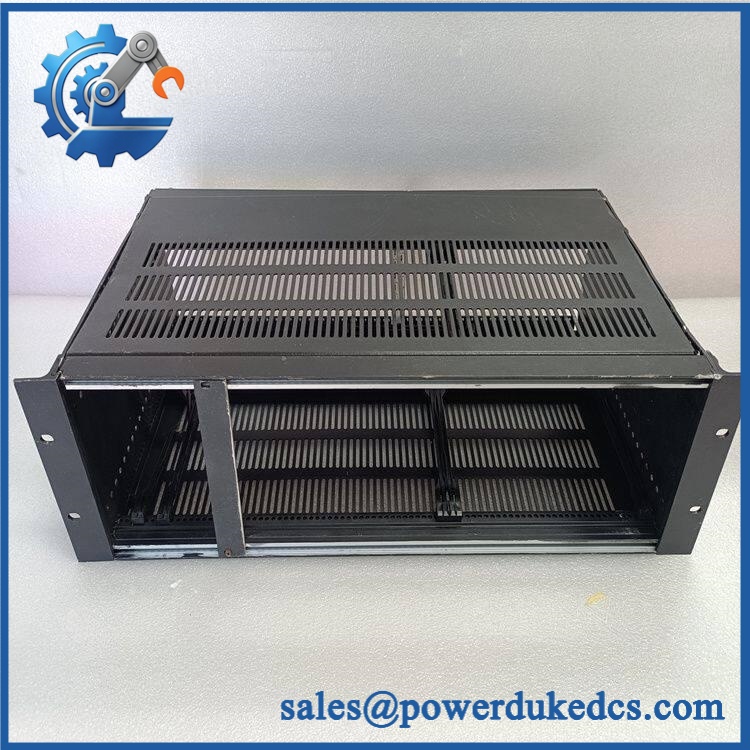
GE WES5162
Quality Assurance SOP
The inspection process should concentrate on mechanical identity and installation condition rather than applying an electronic-module test procedure to a passive frame.
- OEM anti-counterfeit visual inspection: Check GE markings, model identification, labels, manufacturing references where visible, and overall construction against known examples.
- Mechanical condition inspection: Examine the chassis, mounting ears, module guides, connector openings, fastener points, and structural members for cracks, deformation, corrosion, or unauthorized modification.
- Dimensional verification: Measure critical width, height, depth, and mounting interfaces against the customer’s installed configuration.
- Assembly inspection: Confirm that supplied frame hardware matches the quoted configuration and that no guide, bracket, or mounting component is missing.
- Interface alignment check: Verify the physical position of module slots and rear connection areas before packing.
- Load-fit verification: Where test hardware is available, install representative GE modules to check slot engagement, mechanical retention, and connector alignment.
- Documentation control: Record the exact model marking, visible revision information, inspection result, photographs, and packaging condition.
- Pre-shipment protection: Use suitable mechanical protection around rack edges, guides, and connector areas to prevent transit deformation.
Configuration note: The available public evidence for is fragmented, and some listings conflict on whether the designation refers to a frame, a power-related assembly, or a related configuration. For procurement purposes, the safest identification method is to match the full nameplate, physical form, dimensions, and installed GE system documentation rather than relying on “” alone.











 Start Chat


