

Description
- Brand — GE
- Full Model Number — WESDAC D20M++
- System/Series Family — GE WESDAC D20/D200
- Core Function — Main processor board for legacy D20/D200 substation automation and RTU systems
- Top 3 Hardcore Specs — D20 main processor; VME-based D200 architecture; D20 Base software compatibility
- Stock Status — New Surplus / availability subject to physical inventory confirmation
Technical Product Introduction
A failed main processor in a D20/D200 installation can take an otherwise healthy VME rack offline. The GE WESDAC D20M++ is the older-generation main processor associated with the D20/D200 platform; GE’s technical documentation specifically identifies D20M++ as a main processor board and notes that it remains installed at existing locations even though it is no longer available as a current processor generation. The D200 architecture uses a 9-slot VME chassis, while the D20/ platform distributes processing and I/O across the VME system.
The important replacement parameter is software and board-generation compatibility, not simply the D20M++ label. GE’s installation guide documents BootROM revisions for D20M++ boards and specifies jumper settings for compatibility with Base 3.11 or older versus later Base software. In a VME installation, the associated WESTERM D20M++ termination panel also has a defined hardware arrangement and power connection through TB2. Those details make revision verification essential before inserting a replacement board.
Application Scenarios & Field Realities
- At legacy electrical substations, the ++ can remain the processor at the center of an established D20/ RTU installation. The practical maintenance objective is to restore the existing control architecture without unnecessarily disturbing field I/O.
- Where multiple D20 processors communicate through a VME chassis, processor replacement requires more than checking whether the board powers up. GE documentation describes the as a 9-slot VME platform capable of supporting multiple processors and substantial I/O capacity.
- During an emergency processor swap, record the BootROM marking before removing the failed board. GE specifically provides ++ BootROM identification information for determining Base compatibility.
- For sites maintaining older D20/ equipment, retaining a correctly matched ++ spare can be useful when the installed system still depends on the original processor generation. GE’s technical overview confirms that ++ units remain in operation at existing locations.
Migration, Compatibility & Installation Traps
Replacement Matrix
| Replacement condition | Assessment | Engineering requirement |
|---|---|---|
| Same ++ revision with matching Base environment | Drop-in Replacement | Verify BootROM, jumpers, chassis, and existing configuration |
| Different ++ revision | Software Compatible After Verification | Confirm BootROM/Base compatibility before startup |
| ++ replaced by newer D20ME or D20ME II | Hardware and Software Compatibility Review Required | Check system architecture, firmware, peripherals, and configuration |
| Different D20/ platform | Hardware Modification Required | Reassess VME chassis, I/O, communications, and application configuration |
Field Trap 1 — Base software mismatch:
GE documents five WESDAC jumpers, Z1 through Z5, for software compatibility on applicable boards. For /++ systems, the documented settings distinguish Base 3.11 or older from other Base versions. Verify the installed Base version and jumper configuration before commissioning the replacement.
Field Trap 2 — BootROM revision:
Do not assume that two ++ boards with the same front identification are configuration-equivalent. GE provides specific ++ BootROM markings for older Base versions, including 3.02, 3.03, and 3.03A variants.
Field Trap 3 — VME termination-panel configuration:
The VME version uses the WESTERM ++ termination panel, with GE identifying order/layout documentation separately from the + panel. The ++ panel’s power connections are made through TB2. Verify the installed termination-panel arrangement before changing the processor hardware.
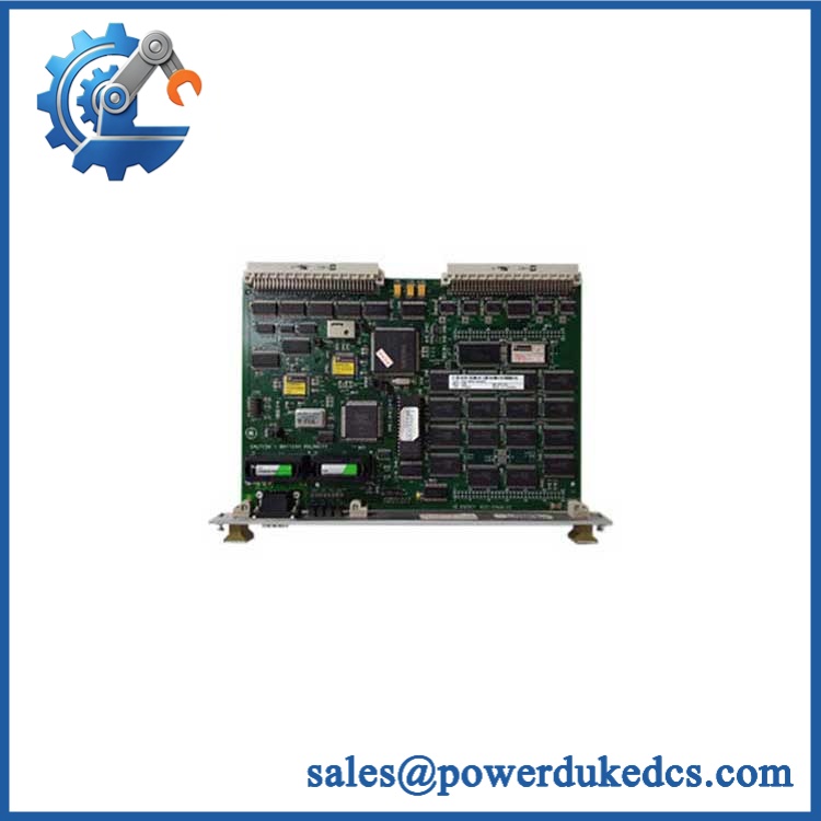
GE WESDAC D20M++GE WESDAC D20M++| D20 Main Processor VME Control Module -…
Quality Assurance SOP
For New Surplus GE WESDAC ++ inventory, the pre-shipment inspection should include:
- OEM anti-counterfeit visual inspection — inspect GE identification markings, ++ designation, PCB construction, connectors, component population, labels, and revision markings.
- Physical-condition inspection — check the VME edge connector, PCB surface, solder joints, mounting hardware, capacitors, and exposed components for corrosion, impact, oxidation, or unauthorized repair.
- Part-number and revision verification — photograph and record all visible board numbers, BootROM labels, and revision identifiers.
- Power-on self-test (POST) — install the board in a compatible D20/ test environment and verify normal startup behavior and available diagnostic/status indicators.
- BootROM verification — confirm that the installed BootROM revision corresponds to the intended test configuration.
- VME bus verification — verify communication between the processor and compatible VME hardware through the test backplane.
- Communication handshake verification — confirm expected communication with applicable D20/ peripheral hardware and maintenance interfaces.
- Configuration verification — check applicable WESDAC jumper settings against the intended Base software environment.
- Functional test record — document processor startup, communication status, board revision, and test results before packing.
- ESD-controlled packing — protect the PCB and VME connector with ESD-safe packaging and mechanical cushioning.
Field note: GE’s current documentation identifies ++ as an obsolete main processor that remains installed in existing D20/ systems. For an actual replacement order, the customer’s BootROM revision, Base software version, chassis type, and existing board combination should be verified before shipment.











 Start Chat


