

Description
- Model: T8403
- Brand: ICS Triplex
- Series: Trusted TMR Safety System
- Part Type: 24 V DC Digital Input Module
- Core Function: Acquires 40 field digital signals through a Triple Modular Redundant architecture, with per-channel diagnostics and fault-tolerant signal processing.
- Key Specs: 40 TMR input channels, selectable line monitoring, 2500 V impulse withstand isolation, and 1 ms Sequence of Events resolution.
Product Introduction
Within a Trusted TMR safety system, the ICS Triplex T8403 sits at the field-input interface and converts 24 V DC discrete signals into redundant input data for the safety controller. Each of its 40 input channels is triplicated, allowing the system to detect and tolerate certain individual circuit faults while maintaining a valid process signal. Built-in diagnostics, configurable line monitoring, and 1 ms SOE capability make the module particularly useful where event timing and fault identification matter (especially in safety-critical shutdown systems).
For plants maintaining legacy Trusted installations, the T8403 is also a practical legacy migration and spare-parts consideration. Its online replacement capability was designed around Companion Slot or SmartSlot arrangements, reducing the need for unnecessary process interruption during module replacement.
Core Technical Specifications
| Parameter | Value |
|---|---|
| Manufacturer | ICS Triplex / Trusted |
| Model | T8403 |
| Product Type | Trusted TMR 24 V DC Digital Input Module |
| System Architecture | Triple Modular Redundant (TMR) |
| Input Channels | 40 |
| Input Signal | 24 V DC digital field inputs |
| Input Processing | Triplicated input circuitry with voting/diagnostic processing |
| Line Monitoring | Selectable; supports open-circuit and short-circuit field wiring detection |
| Isolation | 2500 V impulse withstand opto/galvanic isolation barrier |
| Sequence of Events | 1 ms resolution |
| Diagnostics | Automatic diagnostics and self-test |
| Replacement Method | Online hot replacement with supported Companion Slot or SmartSlot configurations |
| Safety Application | Trusted high-integrity safety and control applications |
| Shipping Weight | Approximately 2 kg (supplier-listed figure; verify against packed configuration) |
The 40-channel architecture, line-monitoring functions, isolation specification, SOE resolution, and supported online replacement arrangements are documented in available T8403 product information.
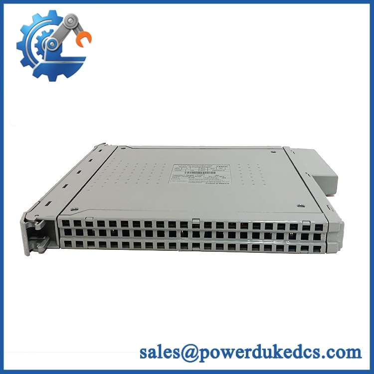
ICS Triplex T8403
Application Scenarios & Pain Points
In a process shutdown application, a single unreliable discrete-input path can create a much larger maintenance problem than the failed field device itself. The T8403 addresses that exposure by processing each field input through a TMR architecture and continuously checking module behavior.
Oil & Gas — Emergency Shutdown Systems
Where hundreds of limit switches, pressure trips, valve-position contacts, and shutdown signals feed a safety system, the 40-channel density helps consolidate discrete field interfaces. With SOE resolution down to 1 ms, engineers can reconstruct the order of closely spaced events during a trip investigation.
Power Generation — Turbine and Boiler Protection
During a protective trip, input integrity is critical. TMR processing provides fault tolerance at the module level, making the suitable for applications in which loss of a single electronic path should not immediately invalidate the reported field state.
Petrochemical Plants — Burner and Interlock Signals
For permissives, valve feedback, interlocks, and discrete shutdown contacts, line monitoring can help identify open- or short-circuit conditions in field wiring (a useful distinction when the process state itself has not changed).
Long-Life Brownfield Sites — Legacy Spare Strategy
When a Trusted installation remains in service well beyond its original procurement cycle, replacement availability becomes a reliability issue in its own right. Current third-party lifecycle listings describe the as discontinued, so plants still dependent on it should treat verified spare inventory as a planned risk-control measure rather than relying on emergency sourcing.
Common Error Symptoms & Diagnostic Symptoms
Because exact Trusted diagnostic reporting depends on the wider system configuration and diagnostic interface, avoid assigning an unverified numeric error code to the . The following field symptoms are more reliable replacement indicators:
Module Fault / Diagnostic Alarm: reports an internal module fault while associated field wiring remains stable.
→ Diagnosis: Possible internal electronics, channel circuitry, or diagnostic-path failure.
→ Action: Confirm system diagnostics and replace the module with a known-good .
Persistent Input Disagreement: One redundant input path repeatedly disagrees with the other TMR paths under a stable field condition.
→ Diagnosis: A channel-specific electronic fault, connector problem, or field-interface problem may be present.
→ Action: Isolate the field circuit, verify wiring, then substitute a tested module if the discrepancy follows the hardware.
Unexpected Line-Monitoring Fault: Open/short-circuit diagnostics remain active even after field wiring has been verified.
→ Diagnosis: Possible input-channel circuitry or interface fault rather than a genuine field-cable defect.
→ Action: Verify terminal connections and configured monitoring parameters; replace the when the fault follows the module.
Cross-Reference & Lifecycle Migration
The is not a generic 24 V DC input card. It belongs to the Trusted TMR architecture, so a conventional PLC digital-input module should not be treated as a functional substitute.
Revision caution: variants such as T8403C appear in the aftermarket, but the existence of a later revision does not by itself establish universal drop-in interchangeability for every Trusted installation. Mechanical fit, firmware level, system configuration, certification status, and existing system node requirements should all be checked before substituting one revision for another.
Firmware: Do not assume that every replacement requires firmware flashing. The correct approach is to compare the installed system’s firmware/software compatibility requirements with the replacement unit before commissioning. Firmware updates should be performed only when the applicable Trusted system documentation calls for them.
Lifecycle status: Current secondary-market lifecycle information identifies the as discontinued/obsolete, while Rockwell Automation continues to identify Trusted as its TMR safety-control technology.
For a running plant, that status changes the stocking calculation. A failed can affect a safety-system repair window, so tested, traceable buffer stock is preferable to waiting for an outage before sourcing a replacement.
Field Engineer’s Tech Notes
Watch the terminal-side configuration. A TMR input module can appear electrically healthy while the actual field termination or configured line-monitoring arrangement is wrong. Before condemning the card, compare the terminal wiring against the approved system drawings and verify the expected field state.
Do not treat hot replacement as a license to pull the module casually. Trusted systems support online replacement under designated Companion Slot or SmartSlot arrangements, but the replacement procedure must match the installed architecture. Follow the site’s approved maintenance sequence and ESD controls rather than assuming every rack position permits the same procedure.
Strict QA & Testing SOP
1. Inbound inspection
Verify model marking, manufacturer identification, serial/date information where available, connector condition, enclosure integrity, and signs of oxidation, contamination, or impact.
2. Traceability check
Record photographs of the nameplate and hardware identifiers. Compare the received unit against the purchase specification and the intended Trusted system revision.
3. Visual and connector inspection
Inspect the field interface, board edge/contact areas, housing, retaining hardware, and status indicators. Particular attention should be paid to bent or contaminated contacts.
4. Live-rig functional test
Install the in an appropriate Trusted test environment. Confirm module initialization, controller recognition, status indications, and diagnostic behavior.
5. Channel verification
Exercise representative digital input channels across the supported 40-channel architecture. Verify that input-state changes are correctly detected and reported.
6. Diagnostic verification
Check module diagnostics and confirm that fault-monitoring behavior is reported correctly. Where applicable, test configured line-monitoring functions rather than simply applying a static input.
7. SOE verification
Where the test facility supports it, verify event capture and confirm the expected 1 ms SOE resolution characteristic.
8. Final QC and packaging
Record test results, photographs, serial information, and technician sign-off. Package the unit in ESD-safe material with adequate mechanical protection for international transport.
9. Documentation package
A professional spare-parts release should include the inspection record and functional test report. Test videos are also available upon request to document power-up, diagnostics, and representative channel testing.
Buyer’s FAQ
Q: Can I hot-swap the while the Trusted system is running?
A: The Trusted architecture supports online module replacement when the installation uses the appropriate Companion Slot or SmartSlot arrangement. The site’s approved replacement procedure must be followed; do not assume every rack configuration supports removal under identical conditions.
Q: How can I verify that a claimed “New Original” is genuine?
A: Check the physical nameplate, model designation, serial/date information, connector condition, manufacturing markings, packaging traceability, and documented test results. For an expensive obsolete safety-system spare, physical inspection and functional testing matter more than a seller’s condition label.
Q: Do I need to flash firmware before installing a replacement?
A: Not necessarily. Firmware requirements depend on the Trusted system version and configuration. Verify compatibility against the installed system documentation before commissioning rather than flashing firmware as a routine step.
Q: What warranty should I expect on a replacement ?
A: Warranty terms depend on the supplier and whether the unit is new, new surplus, refurbished, or used. For a safety-system spare, request the warranty period in writing together with the test report, serial traceability, and stated condition before placing the order.











 Start Chat


