

Description
- Brand: TRICONEX
- Full Model Number: 3503E
- System/Series Family: Tricon v9–v11 TMR safety system
- Core Function: 32-point TMR digital input acquisition for 24 VAC/VDC field signals with built-in diagnostics and self-test
- Top 3 Hardcore Specs: 32 inputs commoned in groups of 8; 20–42.5 VDC recommended input range; <8 ms OFF-to-ON / <15 ms ON-to-OFF response
- Stock Status: Verify current New Surplus, Factory Sealed, or Fully Tested Refurbished condition before order
Module 3: Technical Product Introduction
A failed digital-input card can remove multiple permissives, alarms, status contacts, or shutdown signals from a Tricon controller at once. TRICONEX 3503E is a TMR digital input module with a nominal 24 VAC/VDC input and an integrated self-test function. The Tricon v9–v11 planning documentation specifies 32 input points, commoned in groups of eight, with inputs supporting DC or 47–63 Hz AC signals. Each TMR input module uses three isolated input channels that independently process the field data before the system performs its voting functions.
The electrical thresholds are defined tightly enough for field troubleshooting. The recommended input range is 20–42.5 VDC, with 42.5 VAC/VDC maximum. An OFF-to-ON transition occurs at 15 VAC/VDC typical and 18 VAC/VDC worst case, while the ON-to-OFF threshold is 8 VAC/VDC typical and 6 VAC/VDC worst case. Input delay is specified below 8 ms for OFF-to-ON and below 15 ms for ON-to-OFF, with minimum point isolation of 1,000 VAC / 1,500 VDC through opto-isolation. Diagnostic fault coverage is specified at intervals of 100 ms.
Module 4: Application Scenarios & Field Realities
- Inside a Tricon safety cabinet handling discrete shutdown signals, the 3503E can acquire 32 field states from 24 VAC/VDC circuits. Emergency-stop contacts, limit switches, motor permissives, pressure switches, and alarm contacts are typical examples where the TMR input architecture provides additional diagnostic coverage.
- Where mixed AC and DC field devices exist, the 3503E supports DC and 47–63 Hz AC input signals. That flexibility is useful in legacy Tricon installations, but the actual field voltage should still be measured before replacement because the recommended DC range begins at 20 V and the absolute maximum is 42.5 VAC/VDC.
- For brownfield maintenance, the eight-point commoning arrangement matters. Thirty-two channels do not mean thirty-two independently isolated input circuits; the points are commoned in groups of eight. Review the terminal wiring and common references before assuming that an existing independently isolated field design can be moved directly to this module.
- When intrinsic-safety barriers are part of the field circuit, do not use 3503E automatically. The Tricon documentation specifically warns that this model is not recommended with shunt-diode intrinsic-safety barriers and identifies 3505E for those applications.
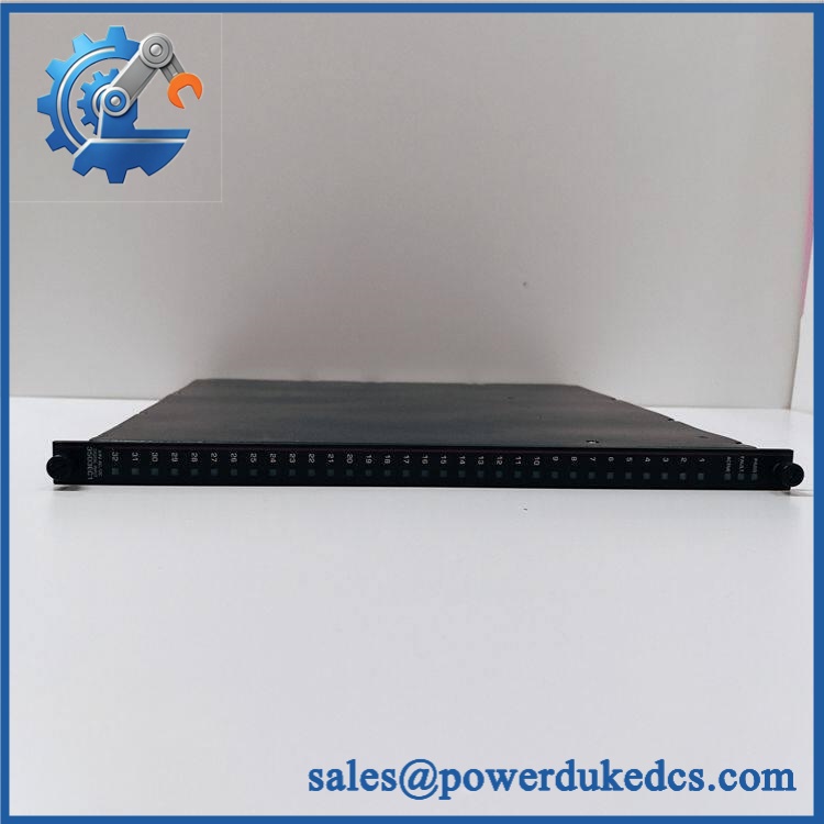
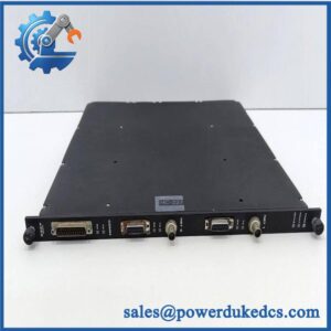
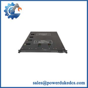
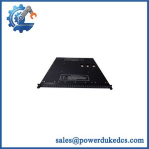
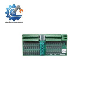
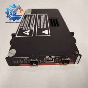
TRICONEX 3503E
Module 5: Migration, Compatibility & Installation Traps
Replacement Matrix
Exact 3503E with matching Tricon configuration: Drop-in Replacement
When the installed system uses the same 3503E module, matching Tricon chassis and termination hardware, compatible firmware, and the same field wiring arrangement, the module can generally be treated as a direct hardware replacement.
3503E hardware revision change: Software Compatible / Configuration Verification Required
Verify the module revision, controller version, diagnostic configuration, and approved project before release. The physical model number alone does not establish full system compatibility.
3505E substituted for 3503E: Hardware Modification Required
Although both modules are 32-point TMR digital inputs, 3505E is the low-threshold variant intended for different field interfaces, including applications using shunt-diode intrinsic-safety barriers. Do not substitute based only on channel count or nominal voltage.
⚠️ Field Traps (Watch Out)
Input-threshold trap: A field signal between the OFF and ON regions can produce unstable or ambiguous behavior. For 3503E, the documented transition region lies between the defined OFF and ON thresholds; a weak supply or excessive wiring resistance can therefore become an intermittent field fault rather than an obvious hard failure.
Commoning trap: The 32 inputs are commoned in groups of eight. Confirm the common/reference arrangement on the existing terminal assembly before installation. A card with the same point count can still be electrically unsuitable if the field wiring was designed around a different isolation topology.
Intrinsic-safety trap: For installations using shunt-diode barriers, the documented recommendation is to use 3505E rather than 3503E. Do not remove or bypass a barrier simply to make the input circuit compatible.
Module 6: Quality Assurance SOP
Pre-Shipment QA Protocol for TRICONEX 3503E
- Step 1 — Identity Verification: Confirm TRICONEX marking, 3503E model number, serial number, hardware revision, production information, and associated baseplate/termination identification.
- Step 2 — OEM Anti-Counterfeit Visual Inspection: Inspect the label, barcode, PCB markings where accessible, module color, connector geometry, retaining hardware, status LEDs, and evidence of unauthorized repair.
- Step 3 — Mechanical Inspection: Check the housing, card-edge connector, alignment/keying features, retaining mechanism, field connector, and enclosure for cracks, corrosion, contamination, or deformation.
- Step 4 — Test Fixture Verification: Prepare an isolated test source capable of supplying the documented 24 VAC/VDC input conditions and verify that the fixture respects the module’s commoned-in-eight channel architecture.
- Step 5 — Power-On Self-Test: Install the module in an approved Tricon test chassis and verify normal startup, module recognition, PASS/FAULT/ACTIVE indications, and absence of diagnostic errors.
- Step 6 — 32-Channel Input Test: Exercise all 32 channels individually using controlled AC and/or DC test signals. Record the recognized state and corresponding status indication.
- Step 7 — Threshold Verification: Test representative channels around the documented switching regions and verify response against the specified OFF-to-ON and ON-to-OFF thresholds.
- Step 8 — Response-Time Test: Apply controlled state transitions and verify the module’s input-delay behavior against the documented <8 ms OFF-to-ON and <15 ms ON-to-OFF values.
- Step 9 — Diagnostic and TMR Verification: Confirm normal diagnostic operation and verify that the three-channel TMR input architecture participates correctly in the approved test configuration without unexplained module or channel faults.
- Step 10 — Final QC Record: Record model, serial number, hardware revision, all 32 channel results, threshold measurements, timing results, diagnostic status, visual condition, test date, and final QC disposition.
Technical Verification Note: Triconex planning documentation identifies 3503E as a 32-point TMR digital input module with 24 VAC/VDC nominal input, commoned in groups of eight, supporting DC or 47–63 Hz AC signals. The recommended input range is 20–42.5 VDC, maximum input voltage is 42.5 VAC/VDC, OFF-to-ON delay is below 8 ms, ON-to-OFF delay is below 15 ms, and input points are opto-isolated with minimum 1,000 VAC / 1,500 VDC isolation. The same documentation specifically cautions against using 3503E with shunt-diode intrinsic-safety barriers and recommends 3505E for those applications.



 Start Chat


