

Description
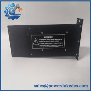
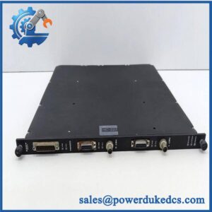
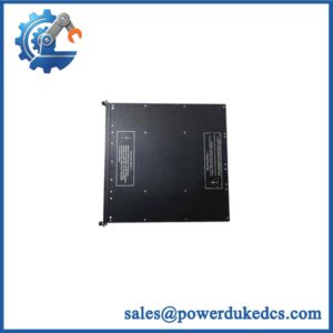
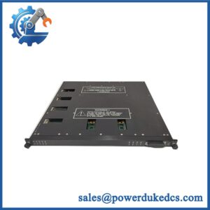
Unboxing & Physical Snapshot
- Manufacturer: TRICONEX / Invensys
- Model: 3625
- Product type: 32-point TMR Supervised/Non-Supervised Digital Output Module.
- Nominal field voltage: 24 VDC.
- Output architecture: 32 commoned digital outputs.
- Approximate dimensions: Approximately 40.8 × 40.8 × 2.2 cm based on a published shipping-size reference; verify the actual module and chassis dimensions before freight planning.
- Estimated module weight: Approximately 1.95 kg from a published inventory reference; use the actual packed weight for freight calculations.
- What’s in the box: 3625 digital output module; field termination hardware, cable assembly, manuals, and other accessories only when specifically included on the purchase order.
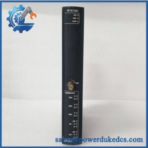
- Front-panel identification: The module uses the dark-blue 3625 identification/color code and has point status indicators plus PASS, FAULT, LOAD, and ACTIVE indications.
- Compatibility warning: Model 3625 is specified for Tricon v10.2 and later systems.
Product Introduction
The TRICONEX 3625 is a safety-system digital output module designed for applications where output states can remain unchanged for extended periods. It provides 32 commoned 24 VDC outputs, with each output command processed through the Tricon TMR architecture and voted before being delivered to the field termination assembly.
This is not a conventional PLC output card. The 3625 incorporates triplicated signal processing and fault-tolerant output circuitry, while field supervision can detect conditions such as missing loads and output-circuit faults (which is particularly important for de-energize-to-trip and energize-to-trip safety functions).
Core Technical Specifications
| Parameter | Value |
|---|---|
| Manufacturer | TRICONEX / Invensys |
| Model | 3625 |
| Product Type | TMR Digital Output Module |
| Output Type | Supervised / Non-Supervised DO |
| Number of Outputs | 32 |
| Output Configuration | Commoned |
| Nominal Voltage | 24 VDC |
| Recommended Voltage Range | 16–32 VDC |
| Maximum Voltage | 36 VDC |
| Maximum Current per Point | 1.7 A ±10% |
| Surge Capability | 7 A for 10 ms |
| Total Output Current | 10 A per termination panel |
| Minimum Required Load | 10 mA |
| Maximum Load Leakage | 4 mA |
| Logic Power Consumption | <13 W |
| Typical Voltage Drop | <2.8 VDC at 1.7 A |
| Point-to-System Isolation | 1,500 VDC minimum |
| Field Termination | 16-point commoned termination panels |
| Point Supervision | Programmable |
| Short/Open Detection | Programmable on supervised points |
| Output Protection | Self-protected against over-voltage, over-temperature, and over-current |
| Diagnostics | PASS, FAULT, LOAD, ACTIVE |
| System Compatibility | Tricon v10.2 and later |
| Color Code | Dark blue |
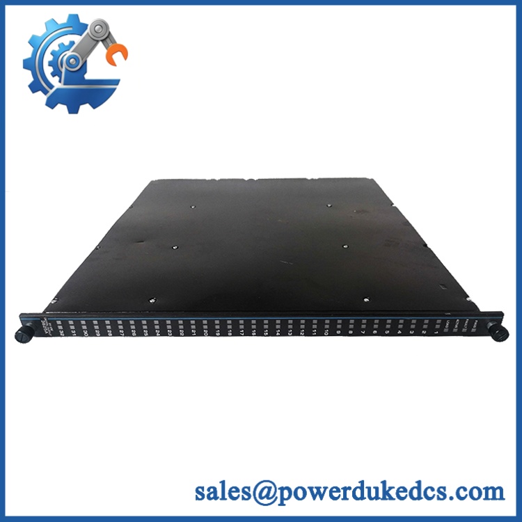
TRICONEX 3625
The 3625 is rated for 16–32 VDC, with 36 VDC maximum and up to 1.7 A per output point. Its logic power requirement is less than 13 W, separate from the energy delivered to field loads.
The module uses 1,500 VDC minimum system-to-field isolation, and the output switches provide internal protection against over-voltage, over-temperature, and over-current conditions.
? Global Compliance & Industry Certifications
The 3625 belongs to a safety-instrumented-system architecture, so compliance documentation should be maintained at both the module and complete-system levels.
- CE Mark: Verify the applicable Triconex/Invensys or current Schneider Electric conformity documentation for the exact revision.
- UL/cUL: Verify the applicable certification record for the specific module revision and Tricon system configuration.
- ATEX/IECEx: Do not assume the individual 3625 module is independently certified for direct hazardous-area installation. Verify the complete certified system and field termination arrangement.
- Marine approvals: DNV or equivalent marine certification should only be claimed when supported by a product-specific approval.
- Functional safety: The Triconex architecture is designed for safety-instrumented applications and TMR fault tolerance; however, the module’s presence alone does not establish SIL compliance for a particular SIF. Application-level validation remains necessary.
- Environmental protection: If the module has been conformally coated or supplied in a particular environmental configuration, verify that condition from the actual product documentation rather than assuming all 3625 units have identical environmental ratings.
The 3625’s TMR design is important because three independent channel paths contribute to the output decision, with voting circuitry used before the field signal is passed onward. That architecture is fundamentally different from simply having three ordinary PLC output channels.
Verify specific lot certifications with OEM.
? Long-Term Storage & Asset Preservation Guide
Keep the 3625 inside its original ESD shielding packaging. Protect the backplane connector and field-interface connections from dust, fingerprints, moisture, and conductive contamination; connector damage can create a diagnostic fault even when the PCB itself remains electrically healthy.
Control humidity below 60% RH where practical. Avoid condensation and rapid temperature changes, particularly for inventory stored near process areas or loading docks. Long-term exposure to corrosive industrial atmospheres can degrade contacts and electronic assemblies.
Preserve the module’s compatibility record. Record the serial number, hardware revision, manufacturing/date code, and associated Tricon system revision. Most importantly, identify the target system as v10.2 or later, since the documentation explicitly restricts 3625 installation to those Tricon versions.
Before installation, inspect the dark-blue housing, front indicators, rear connector, retaining hardware, and module contacts. A stored safety module should be quarantined if there is corrosion, physical deformation, damaged connector hardware, or compromised ESD packaging.
Physical Installation Prerequisites
- Install the 3625 only in a compatible Tricon v10.2 or later chassis.
- Use the designated Tricon backplane position and retaining mechanism; this is not a DIN-rail module.
- Connect the module to the appropriate 16-point commoned field termination panels using the specified Triconex cable assembly.
- Verify that the field termination arrangement matches the 24 VDC commoned-output architecture.
- Maintain adequate cabinet airflow around the module and adjacent Tricon chassis equipment.
- As a preliminary cabinet practice, maintain approximately 50 mm around ventilation paths, unless the Tricon chassis installation drawing specifies a different clearance.
- Verify the 24 VDC field supply remains within the 16–32 VDC recommended operating range.
- Do not exceed the 36 VDC maximum.
- Check the field load against the 1.7 A maximum per point and termination-panel current limitations.
- Verify supervised output loads meet the minimum load requirement and do not create nuisance LOAD alarms.
- Confirm whether each point is configured for supervised or non-supervised operation before field wiring is energized.
- Verify the intended energize-to-trip or de-energize-to-trip philosophy against the approved SIF design.
- Perform the required Tricon diagnostics and proof-test procedures after replacement before returning the safety function to service.
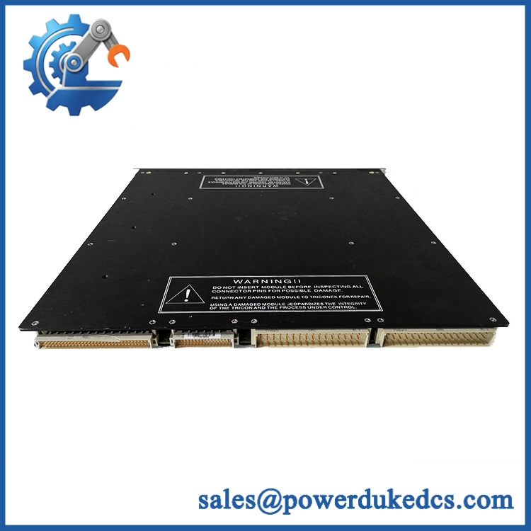
TRICONEX 3625
Buyer’s FAQ
Which HS tariff code should be used for TRICONEX 3625?
A published commercial listing assigns 8537101190, but this should be treated only as a classification reference, not a universal customs ruling. The final HS classification should be confirmed against the destination country’s tariff schedule and the module’s declared function as a safety-system digital output assembly.
What should be declared as the Country of Origin?
Use the actual COO supported by the physical unit and traceability documentation. One commercial listing identifies the origin as the United States, but that information should be verified against the specific module and manufacturer records before being used on a commercial invoice.
Should the shipment be insured?
For a 3625 supporting an operational SIS, insurance is advisable when replacement cost and downtime exposure are significant. Use ESD protection, anti-static cushioning, and a rigid carton; photograph the serial-number label, front indicators, connector, and packaging condition before dispatch.
Does the 3625 include the latest firmware?
Do not treat the 3625 as a conventional firmware-dependent CPU module. It is a digital output module with onboard I/O processing and diagnostic circuitry. Compatibility is primarily governed by the Tricon system generation, module revision, field termination arrangement, and system configuration. The published documentation specifically limits the 3625 to Tricon v10.2 and later.
Inventory-control recommendation: Record the full TRICONEX 3625 identity together with system compatibility, hardware revision, serial number, date code, and field-termination type. Do not substitute a 3625A without engineering review, even though later documentation identifies the 3625A as compatible with 3625 applications; its field-power arrangement is modified into groups of 16 points.



 Start Chat


