

Description
- Brand: Triconex / Invensys
- Full Model Number: 3505E
- System/Series Family: Tricon v9–v11
- Core Function: 32-point commoned 24 VDC TMR digital input acquisition with low switching thresholds and self-test diagnostics
- Top 3 Hardcore Specs: 32 input points; 20–42.5 VDC recommended range; 10 VDC typical Off-to-On threshold
- Input Configuration: Commoned in groups of 8
- Switching Level: 10 VDC typical Off-to-On; 5 VDC typical On-to-Off
- Nominal Turn-On Current: 3–5 mA
- Input Impedance: >1.25 kΩ nominal
- Input Delay: <8 ms Off-to-On; <15 ms On-to-Off
- Point Isolation: 1,000 VAC minimum / 1,500 VDC minimum
- Diagnostics: Stuck-On self-test; maximum diagnostic toggle rate every 100 ms
- Logic Power: <10 W
- Nominal Field-Power Load: 0.5 W per On point; 1.5 W at maximum field voltage
- Status Indicators: One On/Off LED per point; PASS, FAULT, ACTIVE module indicators
- Compatible Termination: Model-specific Tricon termination architecture; 9572-610F is documented for 3505E in Tricon CX v12 installations
- Stock Status: New Surplus or Fully Tested Refurbished; exact hardware revision to be confirmed
Tricon documentation identifies 3505E as a 32-point, 24 VDC, low-threshold TMR digital input module, with inputs commoned in groups of eight and a stuck-On self-test function.
Module 3: Technical Product Introduction
A marginal 24 VDC field contact can create a difficult diagnostic problem when an ordinary digital-input threshold is too high for the actual circuit voltage. The TRICONEX 3505E addresses that condition as a low-threshold TMR digital input module for Tricon systems. It provides 32 input points, commoned in groups of eight, with three independent input channels processing the incoming field data. The module includes a circuit stuck-On self-test, an important feature for de-energize-to-trip applications because the diagnostic system needs a way to verify that an input can actually return to the Off state.
Its threshold specification is the major differentiator from the 3503E. The recommended field-voltage range is 20–42.5 VDC, while the maximum is 42.5 VDC. The typical Off-to-On threshold is 10 VDC, with a 12 VDC worst-case value; On-to-Off is 5 VDC typical and 4 VDC worst-case. Nominal turn-on current is 3–5 mA, input impedance exceeds 1.25 kΩ, and response is below 8 ms Off-to-On and 15 ms On-to-Off. Point isolation is specified at 1,000 VAC minimum / 1,500 VDC minimum.
Module 4: Application Scenarios & Field Realities
- On 24 VDC permissive and status circuits where contact quality is deteriorating, the 3505E’s lower switching threshold can maintain a definite digital state at voltages that would be marginal for a conventional 24 VDC input. The actual voltage should still be measured at the module terminals, not assumed from the nominal field supply.
- For de-energize-to-trip shutdown logic, the stuck-On self-test is particularly important. Tricon documentation describes this diagnostic method as a way to detect an input circuit that cannot reliably recognize an Off state; a controlled zero-input test is applied through the input circuitry while the last valid data is retained by the I/O communication processor.
- When 32 status points share common field returns, remember that the module is organized in groups of eight commoned inputs. This arrangement affects termination planning, cable segregation, and fault tracing. A wiring change that assumes 32 independently referenced inputs can alter the intended circuit topology.
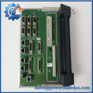
- In newer Tricon CX installations, the 3505E is explicitly shown with the 9572-610F commoned input termination panel in the field-termination documentation. The same documentation illustrates a 3505E connection with one representative point and identifies the module alongside the 3503E and 3503F families.
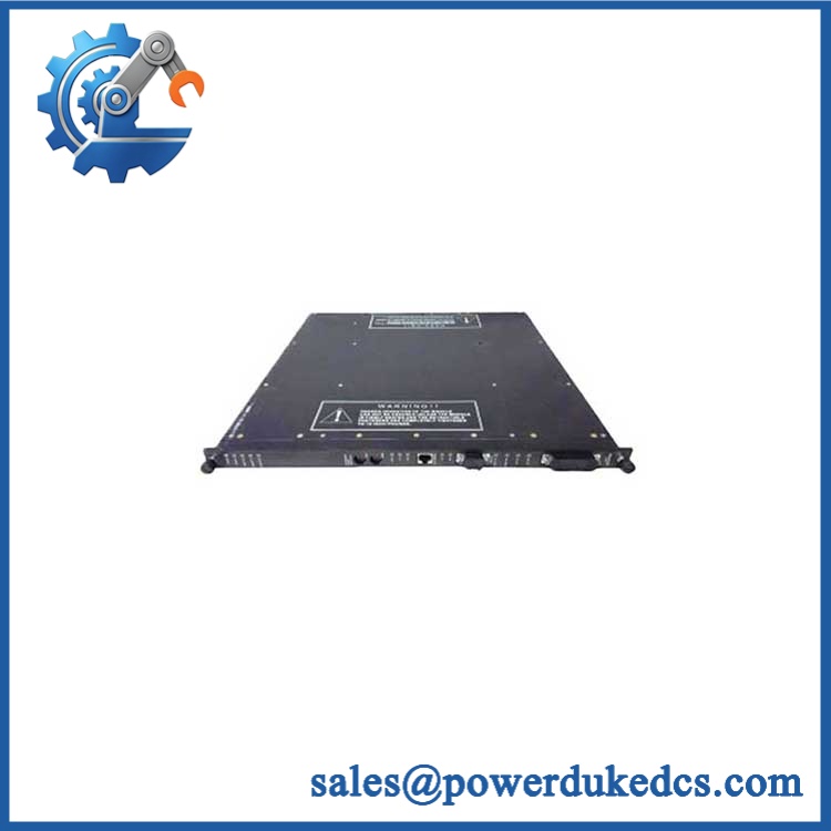
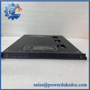
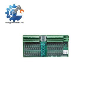
TRICONEX 3505E
Module 5: Migration, Compatibility & Installation Traps
Replacement Matrix
Replacement classification: Drop-in Replacement when the existing system is configured for the same 3505E hardware, compatible Tricon chassis and termination arrangement, field voltage, and documented system revision.
Software compatibility: Configuration verification required. The 3505E is an I/O module rather than a programmable processor, but channel mapping, diagnostic behavior, input logic, and the installed Tricon configuration must match the existing application.
Cross-model replacement: Hardware and configuration verification required. The 3505E is specifically the low-threshold 24 VDC member of the Tricon digital-input family. The 3503E also uses a 24 V-class supply, but it is intended for 24 VAC/VDC operation and has a higher input threshold. These modules should not be substituted simply because both have 32 channels.
Field Traps — Watch Out
1. Do not confuse 3505E with 3503E. Both are 32-point TMR digital-input modules and both are associated with roughly 24 V field systems, but the 3505E is DC-only and low-threshold, while the 3503E is specified for 24 VAC/VDC and uses higher switching levels. This difference can materially change field behavior.
2. Check the actual threshold region during commissioning. A 3505E input around 7–9 V is not automatically a valid steady-state ON signal. The documented typical switching points are 10 VDC for Off-to-On and 5 VDC for On-to-Off, with the transition behavior determined by the module’s hysteresis. Measure the field voltage under the real load condition.
3. Preserve the commoned groups of eight. The module’s 32 channels are not independently referenced. Field returns and common connections must remain consistent with the approved termination drawing; otherwise, a wiring fault can affect more than one logical input point.
4. Do not disable or ignore the self-test behavior. The stuck-On diagnostic is part of the module’s intended safety architecture. During maintenance, verify that the installed system’s diagnostic configuration and permitted point toggling are compatible with the approved test procedure. Tricon documentation specifies a maximum diagnostic toggle rate of every 100 ms and also defines minimum toggle requirements for diagnostic fault coverage.
Module 6: Quality Assurance SOP
Pre-Shipment Inspection Protocol for TRICONEX 3505E
- OEM identity inspection: Verify Triconex/Invensys marking, exact 3505E designation, hardware revision, serial number, front-panel labeling, and additional assembly identifiers.
- Variant verification: Confirm the unit is specifically 3505E, not 3503E, 3504E, 3505F, or another Tricon digital-input variant.
- Mechanical inspection: Examine the housing, module guides, locking mechanism, card-edge/backplane interface, front-panel LEDs, and accessible PCB surfaces for corrosion, contamination, deformation, cracked components, or unauthorized repair.
- Termination verification: Confirm the intended Tricon termination arrangement; for Tricon CX applications, verify compatibility with the documented 9572-610F commoned-input termination architecture.
- Power-on self-test: Install the module in a compatible Tricon test chassis and verify startup behavior, including PASS, FAULT, ACTIVE, and individual point indications.
- 32-channel verification: Exercise all 32 inputs independently while preserving the documented commoned-group architecture.
- DC input test: Apply calibrated 24 VDC-class signals within the specified 20–42.5 VDC recommended range and verify correct channel-state recognition.
- Low-threshold test: Apply controlled voltages around the 5–12 VDC switching region and document Off-to-On and On-to-Off behavior for representative channels.
- Turn-on current verification: Validate nominal input-current behavior within the documented 3–5 mA range under the applicable test configuration.
- Timing verification: Apply controlled transitions and confirm response within the published <8 ms Off-to-On / <15 ms On-to-Off limits.
- Isolation verification: Perform an approved controlled isolation test against the specified 1,000 VAC / 1,500 VDC minimum point-isolation ratings.
- Stuck-On diagnostic verification: Use an approved Tricon diagnostic procedure to verify detection of a controlled stuck-On condition and confirm that the expected diagnostic response is generated.
- Diagnostic coverage check: Confirm compliance with the applicable input-toggle requirements documented for the 3505E.
- TMR verification: Where the test bench permits, validate the three independent input channels and confirm correct data transfer into the Tricon voting architecture.
- Field-power test: Apply representative multi-channel loading and monitor the documented nominal field-power behavior of approximately 0.5 W per On point and 1.5 W at maximum field voltage.
- Thermal observation: Operate a representative number of channels for an extended interval and monitor for abnormal temperature rise, unstable input states, diagnostic faults, or intermittent channel behavior.
- Final QC record: Record exact model, revision, serial number, test chassis, termination interface, input voltages, all 32 channel results, threshold measurements, timing results, diagnostic results, isolation results, test duration, and inspector approval.
- ESD-controlled packaging: Place the module in an ESD-safe package and protect connectors, locking features, LEDs, and PCB surfaces from impact, moisture, contamination, and electrostatic discharge.
Procurement note: The technically supported identity is TRICONEX 3505E — 32-point, 24 VDC low-threshold TMR Digital Input Module. Published Tricon specifications identify 20–42.5 VDC operation, 10 VDC typical Off-to-On switching, 5 VDC typical On-to-Off switching, 3–5 mA nominal turn-on current, >1.25 kΩ input impedance, <8 ms / <15 ms response, 1,000 VAC / 1,500 VDC point isolation, and stuck-On self-test capability. The module is commoned in groups of eight and should be matched to the appropriate Tricon termination architecture.



 Start Chat


