

Description
- Brand: TRICONEX
- Full Model Number: 3511-PI / 3511
- System/Series Family: Tricon v9–v11 TMR safety system
- Core Function: High-frequency pulse acquisition from magnetic speed sensors for turbine, compressor, and rotating-equipment speed measurement
- Top 3 Hardcore Specs: 8 non-commoned inputs; 20 Hz–20 kHz frequency range; 16-bit resolution
- Stock Status: Verify current New Surplus, Factory Sealed, or Fully Tested Refurbished condition before order
Module 3: Technical Product Introduction
A rotating-equipment speed signal is a poor candidate for a conventional digital-input card. The TRICONEX 3511-PI, identified in technical documentation as Model 3511 Pulse Input Module, is designed specifically for high-frequency pulse acquisition from magnetic speed sensors used on equipment such as turbines and compressors. The module provides eight non-commoned pulse inputs and processes voltage transitions from magnetic transducers to determine frequency or RPM, which is then transmitted to the Tricon Main Processors. Its three isolated input legs independently process the incoming data before the TMR controller architecture performs the required voting.
For speed measurement, the bandwidth and measurement resolution are the important numbers. Triconex documentation specifies a 20 Hz to 20 kHz input-frequency range, 16-bit resolution, and typical 25 ms input update rate. Accuracy is specified at ±0.01% from 1,000 to 20,000 Hz and from 100 to 999 Hz, while the 20–99 Hz range is specified at ±1.0%. The balanced differential, AC-coupled input accepts approximately 1.5–200 V peak-to-peak normal-mode signals, with ±150 VDC continuous overrange protection and a typical 0.5 V peak-to-peak sine-wave sensitivity.
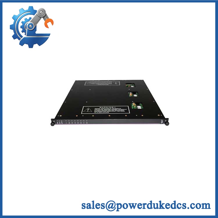
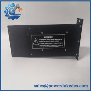
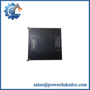
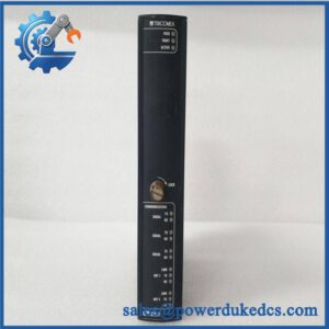
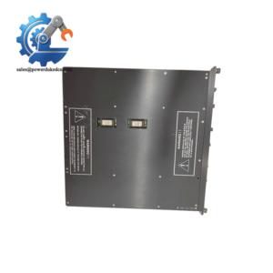
TRICONEX 3511-PI
Module 4: Application Scenarios & Field Realities
- On steam turbines and gas turbines, the 3511-PI is intended for magnetic pickup signals generated by rotating teeth on a shaft-mounted gear. The sensor produces a frequency proportional to shaft speed, allowing the Tricon controller to derive RPM without converting the pulse train into a conventional analog signal first.
- For compressor speed monitoring, the eight non-commoned inputs permit separate speed-sensor circuits to be connected to the same pulse-input module. The high-frequency input range extends to 20 kHz, while the module processes each input through its own isolated channel.
- During brownfield replacement of an existing 3511, sensor amplitude is one of the first measurements to verify. The published normal-mode range is 1.5 to 200 V peak-to-peak, with typical sine-wave sensitivity around 0.5 V peak-to-peak. A weak or excessive pickup signal can therefore be mistaken for a faulty module when the actual problem is sensor air gap, damaged teeth, shielding, or cabling.
- When total pulse accumulation is required, do not use the 3511-PI simply because it accepts pulses. Triconex documentation explicitly states that the Pulse Input module is intended for speed measurement and does not provide pulse totalization; Model 3515 is the specified alternative for pulse-totalizer applications.
Module 5: Migration, Compatibility & Installation Traps
Replacement Matrix
Exact 3511-PI / Model 3511 with matching Tricon configuration: Drop-in Replacement
For an existing Tricon installation using Model 3511, the approved termination assembly, compatible controller configuration, and matching speed-sensor wiring, the replacement can generally be treated as a direct hardware exchange.
3511 hardware revision change: Software Compatible / Configuration Verification Required
Record the installed module revision and controller configuration before replacement. Verify the approved project, diagnostic settings, and input configuration after installation.
3510 substituted for 3511: Hardware Verification Required
Both are eight-point TMR pulse-input modules, but their documented input-update characteristics differ. The 3510 is specified with a 50 ms typical update rate, while 3511 is specified at 25 ms typical. Do not substitute solely because both modules cover the same general 20 Hz–20 kHz frequency range.
3515 substituted for 3511: Hardware Modification Required
Model 3515 is intended for pulse totalization rather than high-frequency rotating-equipment speed measurement. Its signal architecture and application are different.
⚠️ Field Traps (Watch Out)
Sensor-signal trap: The 3511 uses an AC-coupled balanced differential input. The published normal-mode range is 1.5–200 V peak-to-peak, with a typical 0.5 V peak-to-peak sine-wave sensitivity. Verify the actual magnetic pickup waveform at operating speed rather than checking only continuity.
Mis-compare diagnostic trap: Triconex documentation warns that rapidly or continuously changing inputs can cause channel mis-compare conditions when the three measured values differ by more than 0.5% of full scale. For a speed-sensor problem, inspect sensor alignment, gear condition, signal amplitude, cable routing, and waveform quality before assuming a TMR channel has failed.
Termination trap: The 3511 is used with dedicated Tricon pulse-input termination hardware. The field wiring documentation specifies that unused points must be shorted together and shows recommended terminating-resistor arrangements for magnetic speed-sensor circuits. Follow the applicable field-termination drawing rather than improvising the resistor network.
Module 6: Quality Assurance SOP
Pre-Shipment QA Protocol for TRICONEX 3511-PI
- Step 1 — Identity Verification: Confirm TRICONEX marking, 3511-PI / 3511 designation, serial number, hardware revision, manufacturing information, and associated termination-panel identification.
- Step 2 — OEM Anti-Counterfeit Visual Inspection: Inspect the label, barcode, PCB markings where accessible, connector geometry, module color, fasteners, status indicators, and evidence of unauthorized component replacement.
- Step 3 — Mechanical Inspection: Check the housing, card-edge connector, alignment/keying features, retaining hardware, field connector, and enclosure for cracks, corrosion, contamination, or deformation.
- Step 4 — Test Fixture Verification: Prepare an isolated differential pulse-signal generator capable of producing controlled sine, square, or pulse waveforms across the applicable frequency and amplitude range.
- Step 5 — Power-On Self-Test: Install the module in an approved Tricon test chassis and verify normal startup, module recognition, PASS/FAULT/ACTIVE indications, and absence of diagnostic faults.
- Step 6 — Eight-Channel Pulse Test: Exercise all eight non-commoned inputs individually at representative frequencies and amplitudes. Record input detection, channel indication, and calculated frequency.
- Step 7 — Accuracy Verification: Test representative points across the documented frequency range, including low-frequency, mid-band, and high-frequency conditions. Compare measured values with calibrated reference equipment.
- Step 8 — Sensitivity and Protection Test: Verify response at controlled low-amplitude input levels and confirm the test procedure does not exceed the documented ±150 VDC continuous overrange protection.
- Step 9 — TMR Diagnostic Verification: Confirm all three isolated input legs participate correctly in the approved test arrangement and verify that no unexplained mis-compare or channel diagnostic condition occurs.
- Step 10 — Final QC Record: Record model, serial number, hardware revision, frequency points tested, measured accuracy, input amplitude, channel results, diagnostic status, visual condition, test date, and final QC disposition.
Technical Verification Note: Triconex documentation identifies Model 3511 as a TMR Pulse Input module with eight non-commoned inputs, intended primarily for non-amplified magnetic speed sensors on turbines, compressors, and other rotating equipment. The documented range is 20 Hz–20 kHz, with 16-bit resolution, 25 ms typical update rate, ±0.01% accuracy from 100 Hz through 20 kHz, and ±1.0% accuracy from 20–99 Hz. The AC-coupled balanced differential input supports 1.5–200 V peak-to-peak normal-mode signals, with ±150 VDC continuous overrange protection.



 Start Chat


