

Description
- Brand: GE Multilin
- Full Model Number: 350-E-P1-G1-H-E-S-C-P-2E-D-N
- System/Series Family: Multilin 350 Feeder Protection System
- Core Function: Feeder protection, control, metering, monitoring, and communications
- Top 3 Hardcore Specs: 1 A phase CT inputs; 1 A ground CT input; 125–250 VDC / 120–240 VAC supply
- Protection: Standard overcurrent + voltage and directional protection
- Control: CLP, 50BF, Autoreclose (79), Lockout (86)
- Communications: Ethernet, Modbus TCP/IP, DNP3.0, IEC 60870-5-104, IEC 61850 GOOSE
- Case: Drawout
- Stock Status: New Surplus / Factory-Sealed or Fully Tested Refurbished subject to actual inventory condition
GE’s official 350 documentation confirms the ordering-code structure: P1 = 1 A three-phase current inputs, G1 = 1 A ground current input, H = 125–250 VDC / 120–240 VAC power supply, E = 10 inputs and 7 outputs, S = standard overcurrent protection, C = CLP/50BF/79/86, P = voltage protection plus directional elements, 2E = Ethernet with IEC 61850 GOOSE, and D = drawout design.
Module 3: Technical Product Introduction
When a medium-voltage feeder relay fails, the replacement has to reproduce the original protection scheme—not merely provide the same enclosure dimensions. The GE Multilin 350-E-P1-G1-H-E-S-C-P-2E-D-N is a configured 350 Feeder Protection System with 1 A three-phase current inputs, a 1 A ground-current input, 125–250 VDC / 120–240 VAC auxiliary power, 10 inputs and 7 outputs, plus a drawout case. Its protection package combines standard overcurrent functions with voltage and directional protection, while the C control option adds cold-load pickup, breaker-failure protection, automatic reclosing, and lockout functions.
The communication configuration is equally important. The 2E option provides Ethernet communications with Modbus TCP/IP, DNP3.0, IEC 60870-5-104, and IEC 61850 GOOSE, in addition to the relay’s standard front USB/rear RS485 interfaces. GE’s ordering documentation also specifies that the P1/G1 combination must remain matched; a 1 A phase-current input cannot be paired with a 5 A ground-current option. The drawout configuration further affects replacement procedure and panel integration, so the complete order code should be matched before installation rather than purchasing a generic 350 relay.
Module 4: Application Scenarios & Field Realities
- On medium-voltage distribution feeders, the relay can provide phase, ground, and neutral-related protection while also handling voltage and directional elements. With the P option, the configuration includes voltage protection and phase/neutral/ground directional functions, making the exact CT and VT wiring particularly important.
- For feeders requiring automatic restoration, the C option adds cold-load pickup, breaker-failure protection, automatic reclosing (79), and lockout (86). During commissioning, each control function should be checked against the station protection philosophy rather than enabled simply because the relay hardware supports it.
- Where substation automation uses IEC 61850, the 2E communications configuration supports IEC 61850 GOOSE alongside Modbus TCP/IP, DNP3.0, and IEC 60870-5-104. GOOSE configuration must be validated at the system level; matching the relay’s communication option does not by itself reproduce the existing station’s data set, subscription, or network configuration.
- During a relay replacement in an operating switchgear lineup, the drawout design can simplify physical removal and insertion, but it does not eliminate commissioning work. GE’s installation documentation specifies separate drawout and non-drawout mechanical arrangements, and the relay identification label records the model, serial number, firmware revision, and manufacturing information. Record these details before removing the existing unit.
Module 5: Migration, Compatibility & Installation Traps
Replacement Matrix
| Replacement Case | Classification | Engineering Requirement |
|---|---|---|
| Existing 350-E-P1-G1-H-E-S-C-P-2E-D-N replaced by the identical complete order code | Drop-in Replacement | Verify hardware revision, firmware, CT/VT wiring, settings, and communications configuration |
| Another GE Multilin 350 with the same base architecture but different option code | Software/Configuration Verification | Compare every order-code position before energizing |
| 5 A CT version substituted for this 1 A version | Hardware Modification Required | CT interface and protection settings must be revalidated |
| 1E or standard communication version substituted for 2E | Software/Communications Modification Required | IEC 61850 GOOSE/network configuration must be reassessed |
| Non-drawout 350 substituted for this D-version relay | Hardware Modification Required | Mechanical installation and panel arrangement differ |
Field Traps — Watch Out
1. The 1 A CT configuration is not interchangeable with a 5 A version by assumption.
This model uses P1 phase-current inputs and G1 ground-current input, both rated for 1 A. GE specifically states that the G1/G5 and S1/S5 ground-current options must match the corresponding P1/P5 phase-current configuration. Using the wrong CT-input variant can invalidate the protection configuration.
2. IEC 61850 GOOSE is part of the exact 2E configuration.
A standard 350 or a 1E version should not be treated as equivalent simply because it has Ethernet. GE assigns 2E to the Ethernet configuration supporting Modbus TCP/IP, DNP3.0, IEC 60870-5-104, and IEC 61850 GOOSE. If GOOSE is used for interlocking or fast protection signaling, verify the complete station configuration after replacement.
Installation note: The H power-supply option is specified for 125–250 VDC / 120–240 VAC in GE’s ordering documentation. Isolate the relay according to the site’s protection-system maintenance procedure and verify the actual auxiliary supply before energization.
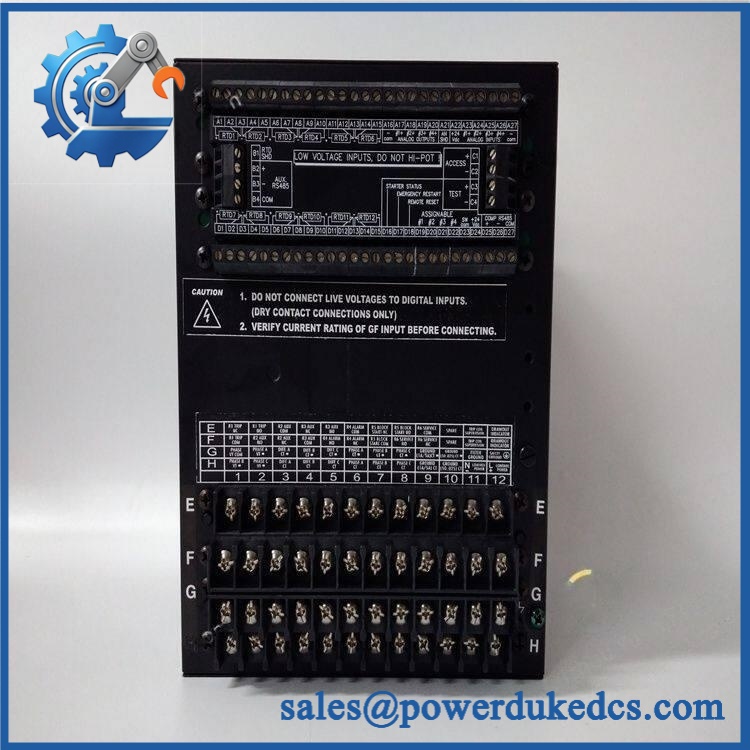
GE Multilin 350 350-E-P1-G1-H-E-S-C-P-2E-D-N
Module 6: Quality Assurance SOP
For a GE Multilin 350-E-P1-G1-H-E-S-C-P-2E-D-N, QA should verify the complete option code rather than testing only the basic relay platform. The order code determines CT inputs, power supply, protection functions, communications, and case design.
- Part-number verification: Confirm the complete designation 350-E-P1-G1-H-E-S-C-P-2E-D-N from the physical product label.
- OEM anti-counterfeit visual inspection: Check GE/Multilin markings, product label, serial number, manufacturing information, connectors, front panel, PCB construction, and revision markings.
- Configuration verification: Decode every option position against the expected configuration: E / P1 / G1 / H / E / S / C / P / 2E / D / N.
- Mechanical inspection: Check the drawout mechanism, rear connectors, front panel, mounting hardware, handle, and enclosure for deformation or damage.
- Power-on self-test (POST): Energize the relay using the correct auxiliary supply and verify the startup sequence, display, status LEDs, and diagnostic indications.
- Input verification: Test the applicable digital inputs and confirm correct state recognition.
- Output verification: Exercise the available relay outputs under controlled test conditions and verify expected pickup/dropout behavior.
- CT input verification: Test the three 1 A phase-current channels and 1 A ground-current input using an appropriate calibrated relay-test system.
- Protection-function verification: Test representative elements included by the S and P options, including overcurrent, voltage, and directional functions, against the approved settings.
- Control-function verification: Where the test environment permits, verify CLP, breaker-failure protection, automatic reclosing, and lockout functions associated with the C option.
- Communication handshake verification: Confirm RS485 communication and Ethernet connectivity, then verify the applicable Modbus/DNP3/IEC 60870 interfaces. For a station using IEC 61850, verify the GOOSE communication path and configured subscriptions in the approved test environment.
- Firmware verification: Record the installed firmware revision and compare it with the customer’s existing relay or approved replacement baseline before deployment.
- Final inspection: Recheck the drawout mechanism, terminals, connectors, front panel, labels, and packaging after testing.
- Traceability: Record the exact order code, serial number, firmware revision, test results, inspection date, and condition classification.
Procurement note: The complete order code is the key identifier here. GE’s official documentation confirms that individual letters and numbers in the 350 code define specific electrical, protection, communication, and mechanical options; therefore, 350-E-P1-G1-H-E-S-C-P-2E-D-N should not be replaced by a generic “GE 350” description alone.











 Start Chat


