

Description
- Brand: ABB
- Full Model Number: LM80
- Product Family: Laser Level Transmitter
- Product Type: Non-contact pulsed-laser level transmitter
- Core Function in System: Continuous level measurement for granular solids and opaque liquids
- Level Measurement Range: 0.5 to 100 m depending on target surface; up to 30 m for dark surfaces
- Positioning Range: Up to 150 m with reflective targets
- Resolution: ±10 mm
- Accuracy: ±30 mm
- Update Rate: Up to 3 readings/s
- Analog Output: 4–20 mA
- Relay Outputs: 2 × SPST
- Communication: RS-232 via standard DB9 for configuration and troubleshooting
- Power Supply: 24 VDC typical; 18–32 VDC
- Supply Current: 0.4 A peak / 0.2 A continuous standard version
- Operating Temperature: -40 to +60°C
- Enclosure: Powder-coated aluminum standard; 316 stainless-steel option
- Weight: 1.6 kg aluminum version
- Condition & Lead Time: Stock condition subject to inspection; emergency dispatch available subject to order confirmation
ABB identifies the LM80 as an intermediate-range, non-contact laser level transmitter using pulsed laser time-of-flight measurement. Its published specifications include 0.5–100 m measurement capability depending on surface characteristics, ±10 mm resolution, ±30 mm accuracy, and a maximum 3 readings/second update rate.
Module 3: Technical Intro & Downtime Impact
A failed level transmitter can become a production-control problem within minutes. Loss of reliable silo, hopper, crusher, or tank level data can cause feed interruptions, overfill risk, empty-run conditions, or unnecessary process shutdowns. ABB LM80 uses pulsed-laser time-of-flight measurement to determine the distance to the material surface without contacting the process material. ABB specifies applications for granular solids and opaque liquids, with level measurement capability extending to 100 m and positioning applications reaching 150 m with reflective targets.
For MTTR, the useful numbers are equally concrete. The LM80 provides ±10 mm resolution, ±30 mm accuracy, up to 3 readings per second, a self-powered 4–20 mA output, and two SPST relay outputs. Power is 24 VDC typical, 18–32 VDC, with the standard version drawing 0.4 A peak and 0.2 A continuously. The aluminum enclosure weighs approximately 1.6 kg, while the instrument operates from -40 to +60°C. ABB recommends an approximately 15-minute settling period after cold start before the internal temperature fully stabilizes.
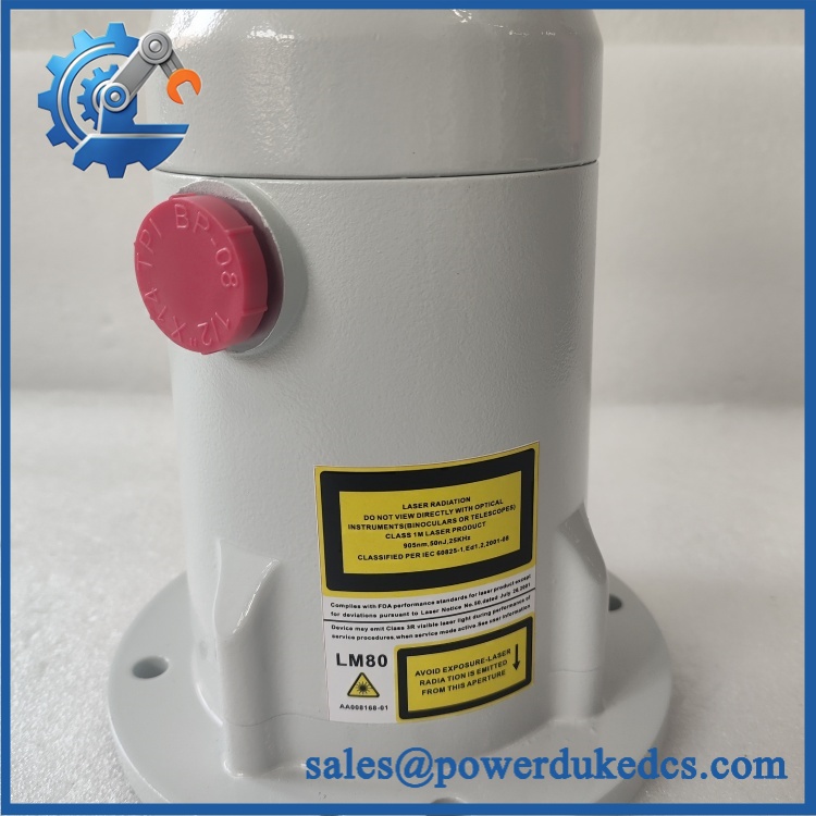
ABB LM80
Module 4: Dynamic Emergency Swap & Configuration Guide
1. Pre-Swap Prep — Confirm the Measurement Geometry
Place the level-control loop into the plant’s approved maintenance condition and isolate the 24 VDC supply before opening the transmitter terminal compartment. ABB explicitly states that the LM80 should not be installed or connected with power applied. Record the mounting flange or process connection, aiming angle, measurement zero/reference point, 4–20 mA scaling, relay setpoints, fail-safe selection, and any LCD2 configuration. Photograph the existing alignment before removal.
2. Removal — Disconnect the Field Wiring and Optical Path Carefully
The LM80 is a process-mounted laser transmitter, not a rack or DIN-rail device. ABB’s mechanical data shows a standard flange base with a 140 mm diameter, a 172 mm overall length, and four 8.5 mm mounting holes; a Tri-Clover process connection is also available.
After power isolation, disconnect the 24 VDC supply, 4–20 mA loop, relay wiring, and RS-232 service connection where fitted. Release the mounting hardware or process connection and remove the transmitter without striking the optical aperture or disturbing the mounting reference.
3. Installation & Configuration — Restore the Original Laser Geometry
Mount the replacement in the same physical orientation and preserve the original reference height and aiming direction. ABB specifies a red laser pointer for alignment and a narrow beam designed for direct targeting. Confirm that the laser reaches the intended material surface without structural obstruction, falling material, or a new mounting shadow.
Restore the original 4 mA and 20 mA setpoints, relay switching points, fail-safe behavior, and safety delay. ABB’s configuration documentation provides a dedicated 4–20 mA test function with selectable 4.00, 12.00, and 20.00 mA values, plus independent relay A/B test functions. For a cold replacement, allow the recommended stabilization period before final acceptance testing.
4. Power-On Self-Test (POST) — Prove Distance and Loop Output
Apply 24 VDC and verify normal startup and distance display. ABB’s commissioning procedure calls for checking a range of measured distances under typical conditions and also recommends testing extreme or abnormal operating conditions before final release.
Use the ‘s built-in 4–20 mA test to command 4, 12, and 20 mA and compare the transmitter output with a calibrated loop meter. Then test relay A and relay B individually. Finally, verify the actual measured distance against a known target and confirm the process level displayed by the control system.
Module 5: Quality Assurance & Testing SOP
Each should receive controlled optical, electrical, mechanical, and loop-performance testing before shipment.
- OEM anti-counterfeit visual inspection: Verify ABB identification, labeling, serial information, enclosure finish, connector arrangement, laser aperture, and mechanical workmanship.
- Exact product verification: Confirm and the physical enclosure/process-connection configuration before dispatch.
- Mechanical inspection: Check the mounting flange, four mounting holes, cable entry, terminal compartment cover, earth connection, optical window, seals, and signs of corrosion or impact.
- Power-on self-test (POST): Apply 24 VDC and verify startup behavior, distance indication, power status, and diagnostic state.
- Distance verification: Use calibrated targets at multiple distances across the intended application range and compare measured distance with the test reference.
- Accuracy test: Verify performance against the published ±30 mm accuracy specification under suitable laboratory conditions.
- Resolution test: Confirm the measurement system responds to controlled target displacement consistent with the specified ±10 mm resolution.
- Update-rate test: Confirm stable measurement updates at the expected operating rate, up to 3 readings/s.
- 4–20 mA full-range simulation: Command 4.00, 12.00, and 20.00 mA through the transmitter test function and compare against a calibrated loop meter.
- Relay test: Force relay A and relay B ON/OFF and verify contact operation against the test condition.
- RS-232 interface test: Verify the DB9 service connection and approved configuration procedure at the documented 19,200 baud, 8 data bits, 1 stop bit, no parity, no flow control settings.
- Laser alignment test: Confirm the visible red aiming laser correctly identifies the intended measurement path.
- Fail-safe test: Verify the configured 4–20 mA fault output and safety delay against the stored application settings. ABB documents selectable fail-safe values of 3.6 mA, 21.00 mA, or last reading, with a safety delay adjustable from 0 to 450 seconds.
- Environmental inspection: Confirm the enclosure and process connection are appropriate for the intended service temperature and installation environment.
- Extended stability test: Operate the transmitter continuously while monitoring distance stability, analog output, relay status, and diagnostic behavior.
- Cold-start verification: Where practical, document the measured output before and after the recommended 15-minute thermal settling period.
- Final QC record: Record serial number, enclosure/process connection, supply measurement, loop readings, distance references, relay results, RS-232 test, photographs, test duration, technician sign-off, and packaging condition.
Module 6: Maintenance & Reliability FAQ
1. Is ABB a direct drop-in replacement, or does it require a firmware flash?
is a complete laser level transmitter, not a conventional programmable PLC card. The normal replacement task is mechanical installation, aiming, loop scaling, relay configuration, and commissioning rather than a firmware flash. ABB provides the LCD2 configuration device and menu-based configuration for 4–20 mA setpoints, relay settings, fail-safe behavior, and other operating parameters.
2. Is it safe to hot-swap the while the system is running?
No. ABB’s installation guidance states that the should not be installed or connected with the power on. Isolate the 24 VDC supply, follow the plant’s instrument-maintenance procedure, and make the field loop safe before disconnecting the transmitter.
3. Will replacing cause my current program or configuration to be lost?
The transmitter does not contain the plant PLC application. The important settings to preserve are the 4 mA and 20 mA distance setpoints, fail-safe output, safety delay, relay switching points, and any application-specific configuration. ABB documents these settings within the configuration menus. Back up or record them before removing the original instrument.
4. What should I verify before commissioning the replacement?
Verify the physical process connection, mounting geometry, measurement reference, power supply, loop wiring, relay wiring, and 4–20 mA scaling. Then check the actual laser target and alignment. ABB specifies 0.5–100 m measurement capability depending on surface characteristics, ±30 mm accuracy, and ±10 mm resolution. Allow approximately 15 minutes of thermal stabilization before making the final accuracy judgment after a cold start.
5. What are the warranty terms if the unit fails after installation?
Warranty coverage should be stated on the quotation or sales order for the specific serialized transmitter. Retain the incoming inspection record, serial number, mounting configuration, laser-alignment photographs, 4–20 mA measurements, relay test results, and post-installation distance verification. For a level transmitter, these records help distinguish an instrument failure from target-surface changes, optical contamination, alignment errors, loop wiring problems, or incorrect scaling.











 Start Chat


