
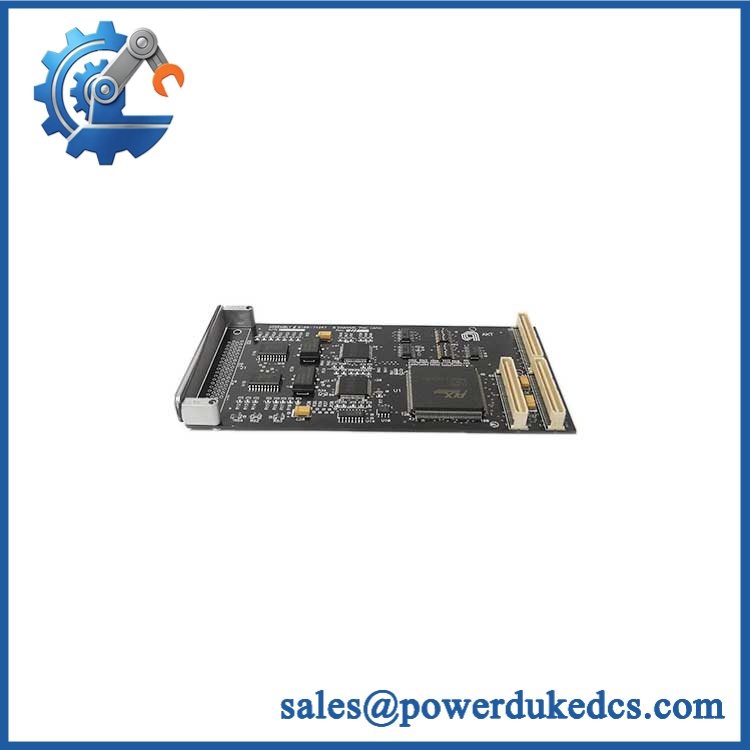

Description
- Brand: DEIF
- Full Model Number: DELOMATIC-3 DGU2
- System/Series Family: DELOMATIC-3 Multi-function System
- Core Function: Generator control, protection, synchronization, load sharing, and power-management functions within a modular DGU
- Top 3 Hardcore Specs: Up to 690 VAC direct measurement; 40-70 Hz measurement range; 24 VDC +30%/-25% system supply
- Generator Capacity: Up to 8 parallel-running generators within the DELOMATIC-3 system architecture
- Current Measurement: CT input, ../1 A or ../5 A AC
- AC Measurement Accuracy: Class 1 to IEC 688
- Analog Inputs: 0(2)-10 VDC and 0(4)-20 mA
- Binary Inputs: Galvanically separated contacts
- Relay Outputs: 250 VAC / 5 A; 1 A DC
- Analog Output Options: ±20 mA; ±10 VDC; 0(4)-20 mA; 0(2)-10 VDC
- Power Supply: 24 VDC +30%/-25%, 32 VDC maximum
- Environmental Operating Range: -25°C to +70°C
- Protection: IP20 for DGU-mounted modules; IP52 for control-panel front
- System Status: Legacy product; DEIF marks Delomatic-3 as no longer for sale
DEIF’s official Delomatic-3 documentation defines each DGU as a generator unit built from a 19-inch dual-height rack containing application-specific plug-in modules. The platform provides generator protection, synchronization, load sharing, breaker control, and power-management functions.
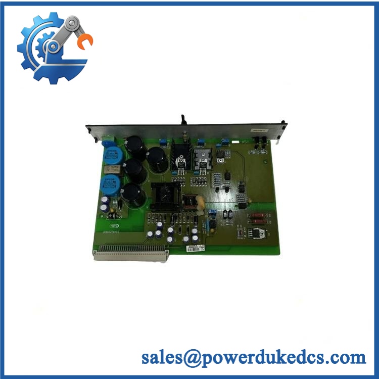
DEIF DELOMATIC-3 DGU2
Module 3: Technical Product Introduction
A generator control system has to coordinate electrical measurements, breaker commands, protection, synchronization, and engine-related functions without separating those tasks into unrelated controllers. The DEIF DELOMATIC-3 DGU2 belongs to the DELOMATIC-3 generator-unit architecture, where each DGU is configured from plug-in modules according to the generator’s specific control and protection requirements. DEIF documents the system for control and protection of up to eight parallel-running generators, with DGU-to-control-panel communication through the system ARCnet connection.
The electrical specification is defined at the DELOMATIC-3 system level. AC voltage measurement is supported up to 690 VAC direct, with other ranges available through voltage transformers; current measurement uses ../1 A or ../5 A CT inputs. Frequency measurement covers 40-70 Hz, and electrical measurement accuracy is Class 1 according to IEC 688. The system accepts 0(2)-10 VDC and 0(4)-20 mA analog inputs, provides relay outputs rated at 250 VAC / 5 A or 1 A DC, and supports configurable analog outputs through the AOM-1 module. The DC supply is 24 VDC +30%/-25%, with 32 VDC maximum.
Module 4: Application Scenarios & Field Realities
- For marine generator switchboards, DELOMATIC-3 combines generator measurement, synchronization, load sharing, breaker control, and protection within the DGU architecture. DEIF documents the system specifically for shipboard applications as well as power-station installations.
- When several generator sets operate in parallel, the DGU architecture supports coordinated power management. DEIF states that the system measures generator power and can start or stop generators according to demand, with start priority selectable by the user or based on running-hour counters.
- For bus-tie or mains-breaker applications, the system can perform synchronization and load ramping before breaker operation. During commissioning, voltage, frequency, phase relationship, breaker feedback, and the configured synchronization logic should be checked together rather than testing the relay outputs in isolation.
- During legacy Delomatic-3 maintenance, module configuration is a major field consideration. The DGU is a modular rack, and DEIF lists separate PSM-1, CM-2, SCM-1, SCM-2, CRM-1, IPM-1, binary-output, and AOM-1 modules. Replacing a DGU-related assembly without documenting its complete module population can change system functionality even when the rack itself remains mechanically compatible.
Module 5: Migration, Compatibility & Installation Traps
Replacement Matrix
Replacement classification: Drop-in Replacement only when the customer’s equipment specifically requires the same DELOMATIC-3 DGU2 configuration and the complete module population, rack, control-panel arrangement, firmware/application configuration, and wiring remain compatible.
Software compatibility: Configuration verification required. DELOMATIC-3 setpoints and timers are user-configurable through the control panel, and the specific DGU function depends on its installed module combination. A hardware replacement therefore requires verification of the stored application parameters and configured generator functions.
Cross-model replacement: Hardware and configuration verification required. DGU1, DGU2, and other DEIF generator-unit references should not be treated as interchangeable based only on the DGU designation. The installed measurement, synchronization, protection, and communication modules determine the actual system function.
Field Traps — Watch Out
1. Do not treat DGU2 as a single universal electronics card. DEIF describes a DGU as a 19-inch dual-height rack containing multiple plug-in modules. The actual module population is selected according to the generator application. Record the complete rack configuration before approving a replacement.
2. Verify the voltage and current measurement circuits. The system supports direct measurement up to 690 VAC, while other voltage ranges require voltage transformers. Current measurement is based on ../1 A or ../5 A CTs. A replacement must therefore match both the system module and the connected transformer ratios.
3. Protect the ARCnet communication path. DEIF specifies communication between DGU units and control panels through a coaxial ARCnet connection. Damage, poor termination, or incorrect cabling can create system-wide communication symptoms that may be mistaken for a failed control module.
4. Do not ignore the 24 VDC supply tolerance. The documented system supply is 24 VDC +30%/-25%, with 32 VDC maximum. Verify voltage at the DGU terminals under load, not only at the cabinet power-supply output.
5. Confirm the environmental envelope. DEIF specifies -25°C to +70°C operational temperature and IP20 protection for modules installed in the DGU rack. Enclosure design, ventilation, condensation control, and cabinet installation therefore remain part of the overall equipment qualification.
Module 6: Quality Assurance SOP
Pre-Shipment Inspection Protocol for DEIF DELOMATIC-3 DGU2
- OEM identity inspection: Verify DEIF marking, DELOMATIC-3 designation, DGU2 identification, serial number, hardware revision, and all visible rack/module labels.
- Configuration inspection: Photograph the complete DGU rack and document every installed module, including PSM-1, CM-2, SCM-1/SCM-2, CRM-1, IPM-1, AOM-1, and binary-output modules where fitted.
- Mechanical inspection: Examine the rack, card guides, connectors, mounting hardware, terminal interfaces, control-panel connections, and module retainers for corrosion, deformation, contamination, or mechanical damage.
- Connector inspection: Check all backplane, module-to-module, control-panel, and ARCnet connection points for oxidation, damaged contacts, loose hardware, or contamination.
- Power-input verification: Confirm the laboratory supply is set to the documented 24 VDC nominal range and remains below the 32 VDC maximum.
- Power-on self-test: Energize the complete DGU configuration in a compatible test arrangement and check startup behavior, module status, abnormal current draw, and fault indications.
- AC voltage measurement test: Apply calibrated three-phase voltage signals within the applicable measurement range and verify correct acquisition and scaling.
- Current measurement test: Inject representative ../1 A and ../5 A CT-derived signals and verify correct measurement response and scaling.
- Frequency verification: Test representative frequencies across the documented 40-70 Hz range and record measured deviation.
- Measurement accuracy check: Compare representative voltage, current, power, and frequency measurements with calibrated standards using the applicable Class 1 measurement requirement as the reference.
- Binary-input verification: Exercise representative binary inputs and confirm correct state recognition and galvanic separation.
- Relay-output verification: Test each configured relay output under a controlled load within the 250 VAC / 5 A AC and 1 A DC contact ratings.
- Analog-output verification: Where an AOM-1 module is fitted, test the configured ±20 mA, ±10 VDC, 0(4)-20 mA, or 0(2)-10 VDC output ranges.
- Synchronization test: Connect an appropriate generator/bus simulation and verify voltage, frequency, and phase-matching logic before simulated breaker closing.
- Load-sharing test: Where the test system permits, simulate multiple generator units and confirm power-sharing behavior and configured start/stop logic.
- Breaker-control test: Verify generator breaker, mains breaker, and tie-breaker command and feedback paths according to the installed configuration.
- Protection-function test: Exercise the applicable over/under-voltage, frequency, current, and other configured protection functions using controlled simulated faults.
- ARCnet communication verification: Confirm stable communication between the DGU and control panel through the configured ARCnet network.
- Control-panel verification: Confirm display, pushbuttons, status LEDs, alarm indications, setpoints, and timer functions where the supplied configuration includes a compatible CP.
- Extended operation test: Run the DGU under representative electrical measurement, communication, and control activity and monitor for resets, communication loss, drift, or intermittent faults.
- Thermal observation: Monitor module and rack temperatures during sustained operation, especially around the PSM-1 and other power-dissipating modules.
- Final QC record: Record DGU identity, complete module population, hardware revisions, power measurements, voltage/current/frequency test results, synchronization results, protection tests, communication results, control-panel results, test duration, and inspector approval.
- ESD-controlled packaging: Protect the complete assembly and individual modules against ESD, connector damage, vibration, moisture, and mechanical shock during shipment.
Procurement note: DEIF’s official documentation identifies Delomatic-3 as a modular generator control and power-management system, with one DGU per generator and application-specific plug-in modules. It supports up to eight parallel generators, measurement up to 690 VAC direct, CT inputs at ../1 A or ../5 A, 40-70 Hz measurement, Class 1 electrical measurement accuracy, 24 VDC system supply, and operation from -25°C to +70°C. DEIF currently marks the Delomatic-3 data sheet as no longer for sale, so complete rack configuration and legacy spare compatibility should be confirmed before approving a replacement.











 Start Chat


