

Description
- Brand: Emerson EPRO
- Full Model Number: PR6423/010-140+CON021
- System/Series Family: EPRO PR6423 Eddy Current Sensor / CON021 Converter
- Core Function: Non-contact shaft displacement and vibration measurement for rotating machinery
- Top 3 Hardcore Specs: 8.0 mm tip diameter; ±1.0 mm position range; 0–20 kHz frequency range
- Additional Key Spec: 8 V/mm sensitivity ±1.0%
- Sensor Temperature Range: -35 to 180°C
- Sensor Agency Rating: CE, CSA, ATEX with appropriate converter configuration
- CON021 Output: -4 to -20 V maximum output range
- CON021 Frequency Range: 0–20 kHz
- CON021 Rise Time: <15 µs
- CON021 Protection: IP20 panel-mount converter
- Stock Status: New Surplus — confirm current warehouse quantity and packaging condition
The PR6423 specifications and electrical data are documented in Emerson’s machinery health documentation.
Commercial-Technical Deep Dive
A shaft-monitoring channel becomes a downtime problem when the probe, converter, and receiving monitor are mismatched. The Emerson EPRO PR6423/010-140 uses eddy-current sensing without physical contact with the shaft. The PR6423 platform measures radial vibration, shaft position, eccentricity, and speed-related signals in rotating equipment. Its 8.0 mm sensing tip is intended for medium-size shafts, with Emerson specifying a minimum shaft diameter of about 25 mm.
The useful number here is the 8 V/mm sensitivity. Across the ±1.0 mm position range, the probe provides approximately a 16 V signal span. That closely matches the converter’s specified -4 to -20 V maximum output range. The converter also provides 0–20 kHz frequency response and a rise time below 15 µs. Those figures matter during transient shaft movement, especially when the channel feeds a machinery protection system rather than a slow process input. —The receiving monitor’s scaling still needs to match the installed probe and converter combination.
Compatibility & Installation Traps
Migration/Compatibility
A replacement of the same PR6423/010-140+ combination normally does not require a firmware flash or PLC logic rewrite. This is a sensor-and-converter measurement chain, not a programmable controller.
It is not a universal drop-in replacement for every variant. Emerson lists different mechanical configurations, measurement characteristics, cable arrangements, and converter combinations. The standard is specified for with a 2.0 mm standard measuring range. Extended-range applications use dedicated variants such as /913-030 or /913-040.
Before installation, verify the probe suffix, mounting thread, cable configuration, converter range, target material, and receiving-channel scaling. For an existing protection loop, compare the installed nameplate before removing the old assembly.
⚠️ Field Traps (Watch Out)
Trap 1 — Converter range mismatch.
Do not replace a matched converter with a visually similar extended-range unit. A different converter range changes the measurement relationship and can produce incorrect channel scaling. Emerson explicitly separates standard and extended-range versions.
Trap 2 — Wiring and polarity errors.
The uses screw terminals for supply and output. Emerson specifies a negative DC supply range of -23 to -32 V and a maximum output range of -4 to -20 V. Treat this as a bipolarity-sensitive instrumentation circuit. Isolate the supply before wiring. Verify polarity and output voltage with a calibrated meter before reconnecting the protection input.
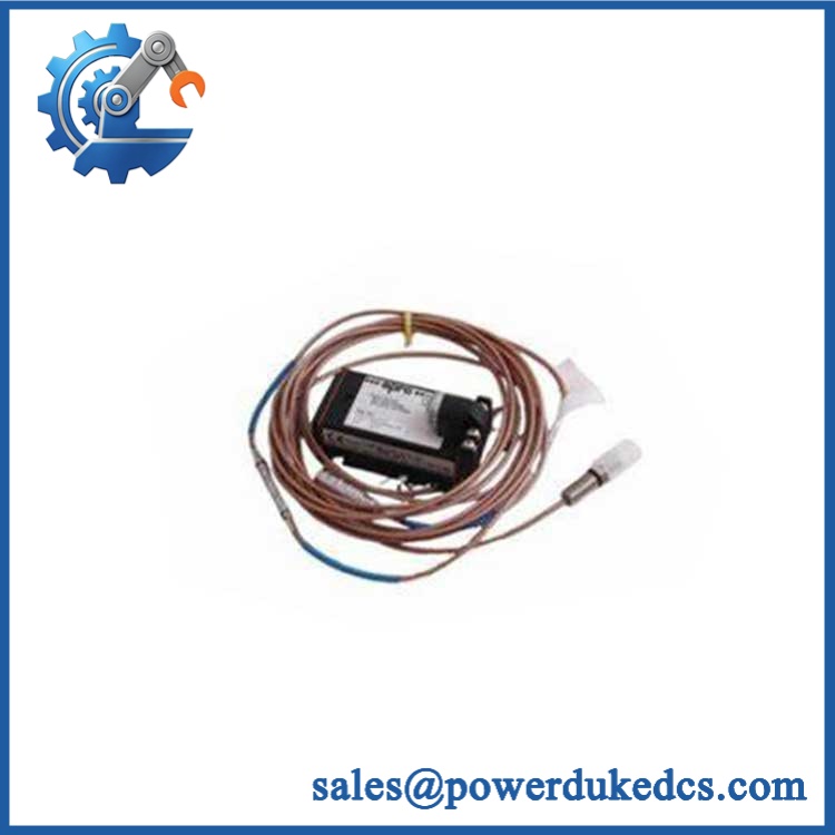
Emerson PR6423/010-140+CON021
Quality Assurance SOP
Every surplus unit should pass a documented inspection sequence before shipment:
- OEM anti-counterfeit visual inspection: Compare nameplate format, model code, markings, connector construction, housing finish, fasteners, and cable termination against known Emerson/EPRO characteristics.
- Part-number verification: Confirm on the probe and on the converter before packing.
- Mechanical inspection: Check probe threads, sensing tip, cable jacket, armor, connector, converter terminals, and mounting points for impact or corrosion.
- Power-on self-test: Apply the specified supply correctly and verify stable converter output. The documentation does not specify ERR/RUN LEDs, so acceptance should not depend on nonexistent indicator behavior.
- Sensor signal verification: Check the complete probe-to-converter signal path against the expected displacement response and polarity.
- Frequency-path verification: Confirm the converter responds across the intended instrumentation bandwidth where suitable laboratory equipment is available.
- Communication handshake verification: Perform this at the complete monitoring-system level when a digital receiving monitor is installed. The itself is an analog signal converter rather than a network communication device.
- Final documentation: Record model number, serial number, inspection result, packaging condition, and shipment photographs.
For surplus inventory, these checks are more meaningful than a simple power-on declaration. They test the actual measurement chain.
CRO-Driven Buyer FAQ
Is Emerson /010-140+ an obsolete part?
The and families are established machinery-monitoring products with documentation dating back many years. Emerson’s published documentation confirms the product architecture and specifications, but it does not establish a current universal lifecycle status for every suffix. For critical projects, verify present OEM availability against the exact part number.
Can I replace the /010-140 without shutting down the machine?
Do not treat this combination as a hot-swappable field device. The uses screw-terminal power and output connections. For maintenance, isolate the relevant supply and follow the plant’s machinery-protection bypass and permit procedures before disconnecting the channel.
Does the /010-140 use a 4–20 mA output?
Not from the output specification. Emerson specifies a -4 to -20 V maximum output range for the converter. This distinction matters when checking the receiving input card or monitor configuration.
What warranty is available?
Warranty duration should be stated on the commercial quotation for the specific stock lot. Technical support covers product identification, documentation review, wiring guidance, and basic application checks. Field commissioning, machinery alignment, protection-setting validation, and site safety remain the customer’s responsibility.
How do I confirm the correct replacement before ordering?
Send the complete existing probe and converter part numbers, including every suffix. A clear nameplate photo is useful for confirming the mechanical and electrical configuration. For this family, matching only the base number is not sufficient because converter range and sensor configuration affect the measurement chain.



 Start Chat


