

Description
- Model & Brand: GE Multilin 239
- Series: 239 Motor Protection Relay
- Part Type: Three-phase AC motor protection relay
- Physical Dimensions: Approximately 123 × 182 × 102 mm (W × H × D behind the panel); the complete bezel/enclosure envelope is larger, and the standard panel cutout is approximately 111 × 175 mm.
- Estimated Shipping Weight: 2.3 kg / 5 lb shipping weight in the documented GE packaging configuration.
- What’s in the Box: GE Multilin 239 relay, protective packaging, and applicable QC documentation. The phase/ground CTs, RS232-to-RS485 converter, optional RTD hardware, analog-output option, shallow-mount collar, and other accessories are configuration-dependent and should not be assumed.
Product Introduction
The GE Multilin 239 is installed on a motor starter or switchgear door as the protective measuring and trip device for a three-phase AC motor. It monitors phase and ground current through external CTs, calculates thermal capacity, and controls dedicated output relays when programmed protection conditions are reached. This architecture makes the 239 a pilot protection device; it does not carry the motor’s primary current.
For an installed legacy motor-management system, the exact configuration matters more than the basic “239” label. The standard relay supports 1 A or 5 A phase CT inputs, isolated two-wire RS485 Modbus RTU, four Form-C output relays, and a universal control-power supply; optional RTD and analog-output functions change the installed feature set (check the rear label before energizing).
Core Technical Specifications
| Parameter | Value |
|---|---|
| Manufacturer | GE Multilin / GE Digital Energy |
| Model | 239 |
| Product Type | Motor Protection Relay |
| Application | Three-phase AC motors and associated mechanical equipment |
| Phase Current Inputs | 1 A or 5 A CT secondary |
| Phase Current Range | 0.1–11 × phase CT primary |
| Phase Current Accuracy | ±2% of full scale |
| Measurement Method | True RMS, 16 samples/cycle |
| Ground Current Inputs | 5 A CT secondary and 50:0.025 input |
| Ground Current Range | 0.03–1.4 × CT primary for 5 A CT; 0.05–16.0 A for 50:0.025 CT |
| Ground Current Accuracy | Configuration-dependent; up to ±2% FS for 5 A CT |
| Phase Current Frequency | 20–300 Hz |
| Thermal Model | Separate start/run protection with exponential cooldown |
| Overload Curves | 15 run curves |
| Locked Rotor Current Range | 0.5–11 × FLC |
| Safe Stall Time | 1–600 s |
| Overload Pickup Range | 0.1–150 A for CT primary <50 A; 1–1500 A for CT primary >50 A |
| Unbalance Range | 5–100% / OFF |
| Short-Circuit Pickup | 1–11 × CT primary / OFF |
| Short-Circuit Intentional Delay | Instantaneous or 10–60000 ms |
| Ground Trip Range | 0.03–1.4 × CT primary for 5 A CT; 0.05–16.0 A for 50:0.025 input |
| Switch Inputs | Dry contacts |
| Switch Input Excitation | Approximately 29 VDC, 10 mA pulsed |
| Output Relays | 4 Form-C relays |
| Relay Contact Material | Silver alloy |
| Relay Contact Rating | Up to 10 A resistive at 120/250 VAC under specified conditions |
| Communications | RS485, 2-wire, half duplex, isolated |
| Protocol | Modbus RTU |
| Baud Rate | 1200–19,200 bps |
| Optional Analog Output | 0–1, 0–20, or 4–20 mA |
| Optional RTD Inputs | Up to 3 RTDs |
| Control Power, Standard | 90–300 VDC / 70–265 VAC, 50/60 Hz |
| Optional Low-Voltage Supply | 20–60 VDC / 20–48 VAC |
| Insulation Voltage | 300 V |
| Dielectric Strength | About 2.0 kVAC for 1 minute to relays, CTs, and power supply |
| Operating Temperature | 0°C to +60°C |
| Storage Temperature | -40°C to +70°C |
| Humidity | 95% RH, non-condensing |
| Pollution Degree | 2 |
| Overvoltage Category | 2 |
| Ingress Rating | IP40 |
| Standard Shipping Box | 215 × 152 × 152 mm |
| Ship Weight | 2.3 kg / 5 lb |
| Fuse | 5 × 20 mm, 2.5 A, 250 V, slow-blow |
| Software | 239PC / later EnerVista support, configuration dependent |
| Firmware | Configuration-dependent and field-upgradeable |
| Hot Swap | Do not assume live replacement |
| Lifecycle | Legacy / Discontinued |
The relay’s control supply is broad on the standard version: 90–300 VDC or 70–265 VAC at 50/60 Hz. A separate MOD501 configuration covers lower-voltage control power. Verify the rear nameplate before applying power because these configurations are not interchangeable assumptions.
The base 239 has four Form-C output relays: Trip, Alarm, Auxiliary, and Service. The trip relay is normally used as the primary protective output, while the other relay functions can be programmed according to the application.
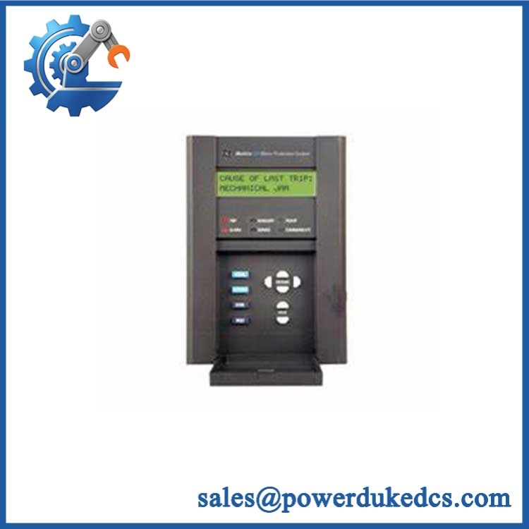
GE 239
🚨 Global Compliance & Industry Certifications
The 239 documentation provides several identifiable compliance and test references:
- UL: Recognized under E83849 for the documented product family.
- CSA: Approved under LR41286.
- ISO 9001: GE documentation states manufacture under an ISO9001-registered/recognized quality system.
- IEC-based testing: Documentation references IEC 255-5 insulation testing, IEC 255-4 disturbance testing, IEC 801-2 static discharge, and IEC 68-2-38 temperature/humidity cycling.
- Class I, Division 2: MOD513 is the specific option identified for Class I Division 2 operation. This is an option/configuration attribute, not a blanket statement that every 239 is Class I Division 2 approved.
- ATEX / IECEx: Do not assume certification for the standard 239 from the North American UL/CSA records. The exact installed configuration and certificate must be verified separately.
- Marine approvals: MOD517 is identified for Australian Mines approval; DNV GL or other marine approval should not be assumed without project-specific documentation.
- CE Mark: Verify the applicable declaration for the exact production configuration; the cited 239 documentation does not establish a universal CE claim for every variant.
- Country of Origin: Establish from actual manufacturing traceability.
- HS classification: Confirm with the importing country’s customs broker.
The Class I Division 2 option matters because the approval governs use in locations where flammable gases or vapors may be present under the specified hazardous-location conditions. Do not convert that statement into a general hazardous-area approval for an arbitrary 239 configuration.
Verify specific lot certifications with OEM.
🚨 Long-Term Storage & Asset Preservation Guide
Keep the 239 in its ESD-protective packaging and protect the rear terminal area from dust and mechanical impact. The relay uses many screw terminals and CT connections, so connector preservation is part of asset preservation, not just cosmetic housekeeping.
There is one unusually important storage instruction in the GE documentation: power up the 239 at least once per year to avoid deterioration of electrolytic capacitors in the power supply. This is the kind of maintenance note that should be incorporated into the warehouse preservation schedule for long-held spares.
Store the relay in a dry, temperature-stable environment without condensation. Although the documented storage environment permits up to 95% RH non-condensing, a practical warehouse target below approximately 60% RH reduces corrosion risk during multi-year storage.
Keep the original configuration information with the asset. The presence or absence of RTD and analog-output options, as well as the control-power option, changes the actual configuration even though the front panel still says “239.”
Physical Installation Prerequisites
The 239 is designed for panel or switchgear-door mounting rather than DIN-rail installation. The standard installation uses eight #6 self-tapping screws, and the relay should be positioned so the front-panel display, keypad, and status LEDs remain accessible to operators.
The documented rear-envelope dimensions are approximately 123 mm wide × 182 mm high × 102 mm deep, while the standard panel cutout is approximately 111 × 175 mm. A reduced-depth mounting collar option changes the mechanical envelope, so the installed hardware should be measured before replacing an existing unit.
Ground terminal 13 must be connected to a reliable system ground using approximately #12 wire or ground braid. The documentation also states that shield terminals and RTD common terminals are internally connected to this safety ground.
For CT circuits, use the specified terminal arrangement and appropriate CT wiring. Never open-circuit an energized CT secondary unless the system has been designed and isolated for that operation.
The 239 has no special ventilation requirement in the cited installation documentation, but do not pack cables tightly against the rear terminals or obstruct service access. Keep the cabinet environment within the specified 0–60°C operating range.
Buyer’s FAQ — Logistics & Compliance Focus
Q: What HS Tariff Code should be used for GE 239?
A: The 239 is an industrial motor-protection relay, but the final Harmonized System classification depends on the importing country’s tariff schedule and customs interpretation. Have the importer or broker confirm the classification before issuing the commercial invoice.
Q: Does the Country of Origin follow the shipping location?
A: No. COO should be supported by manufacturing or traceability documentation for the specific relay or lot. A warehouse or export location does not independently establish manufacturing origin.
Q: Does the GE 239 include the latest firmware pre-loaded?
A: Do not assume it. The documented 239 family has multiple firmware revisions; one GE manual identifies firmware revision 2.7x with 239PC software 2.7x or newer, while earlier documentation identifies 2.6x. The actual firmware is determined by the individual unit’s label and configuration, so record the installed version before replacement rather than assuming a “latest” image.
Q: How should shipping insurance and physical handling be managed?
A: GE’s documented shipping package is approximately 215 × 152 × 152 mm with a 2.3 kg ship weight. Insure the shipment for its documented commercial replacement value, photograph the rear label and terminal condition before dispatch, and use rigid protection around the terminal screws and front bezel; these areas are vulnerable to impact during transit.











 Start Chat


